
TRUCK SERVICE MANUAL
PROPELLER SHAFT
General
The most common causes of vibration are:
flange (vehicles without center bearing, rotate the shaft at
1. universal joint flange or yoke misalignment; 2. parking
the transmission). Reconnect the shaft, then road test the
brake drum out of balance; 3. Out of-balance propeller
vehicle or spin the drive line and check for vibration.
shaft assembly; 4. propeller shaft out of phase; 5.
excessive flange run-out or distorted yokes; 6. loose flange
or yoke rut; 7. excessive vehicle speed.
To correct drive line vibration the propeller shaft must
be checked in such a manner that both balance and
alignment are considered. Never change the drive line
balance or alignment until a thorough check of the most
common causes has been completed.
Drive line vibration can be checked by road testing the
vehicle, spinning the drive line with the vehicle up on floor
stands, or by pulling the rear axle shafts and spinning the
drive line.
CAUTION: Be certain that vehicle is positively
supported.
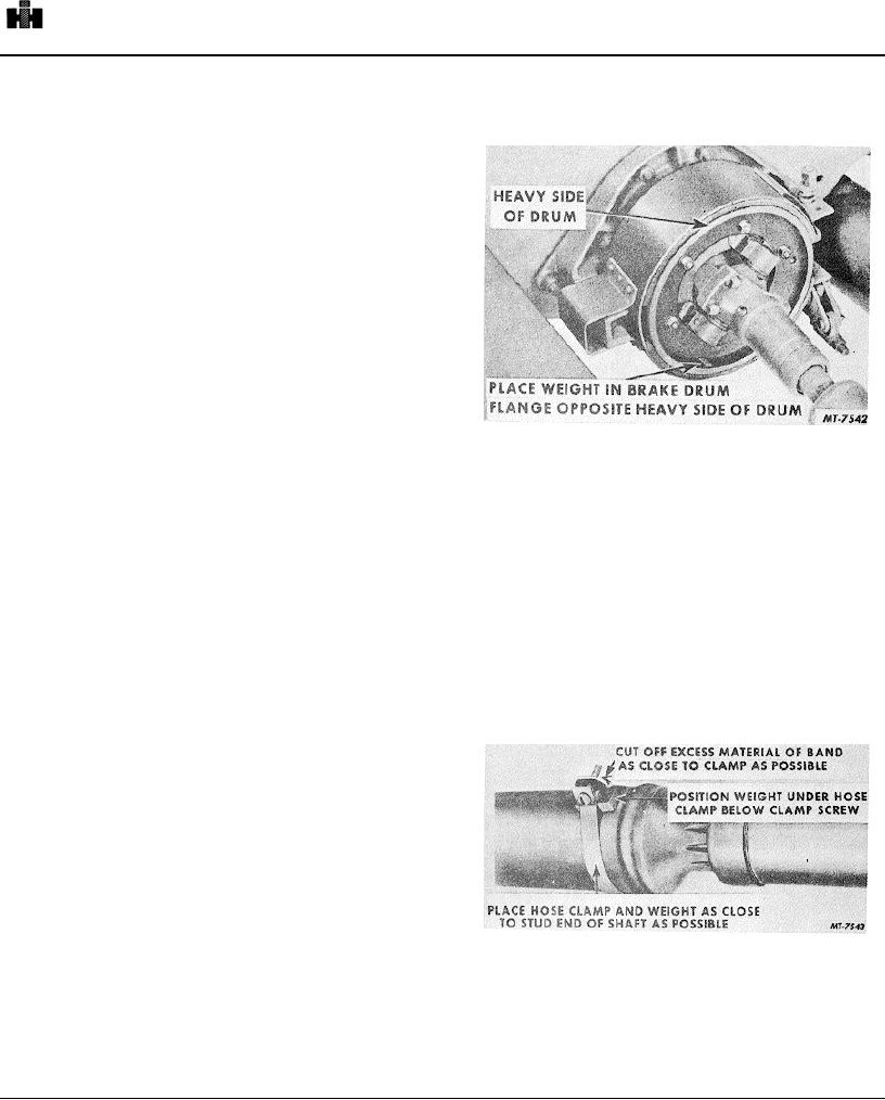
Fig. 7. Balancing Parking Brake Drum
Start the engine and with the clutch disengaged and
the transmission in gear to keep the clutch disc from
If vibration is still present after the above changes, on
spinning, bring engine speed up slowly to governed speed
vehicles with the brake drum at the center bearing place a
to determine if vibration is in the engine itself or due to an
lump of glazer's putty weighing approximately one-half
out-of-balanced clutch pressure plate assembly. If only
ounce at-the brake drum flange, Fig. 7. (A small magnet
normal vibration is evident, disconnect the front propeller
can be used in the brake drum flange in place of putty; a
shaft at the transmission companion flange and with the
1/2 ounce magnet can be obtained by removing the magnet
transmission in direct drive and the clutch engaged, slowly
from a magnet drain plug. ) Road test the vehicle or spin
bring engine speed to governed speed to determine if
the drive line and, by changing the location of the weight,
vibration is caused by an out-of-balance clutch disc or out-
find the point of least vibration. Then increase or decrease
of-balance transmission gears.
this weight at that point to obtain as nearly as perfect a
balance as possible. Weigh the glazer's putty (or magnetic
If both the above checks show only normal vibration,
weight) and install a piece of steel of the same weight in the
connect the front propeller shaft and use the following step-
same location by tack welding the weight to the inside of
by-step procedure in balancing the drive line assembly.
the brake flange. Hold the weld material to a minimum.
BALANCING THE DRIVE LINE
There are three methods of balancing the drive line and
these are:
1. By rotating the propeller shaft 180 in relation to the
companion flange.
2.
By adding a small weight to the parking brake drum.
3.
By adding a small weight to the propeller shaft.
Each of these methods is covered in detail in the following
Fig. 8. Balancing Propeller Shaft
paragraphs.
For vehicles without a brake drum at the center bearing
Before any balance weights are added to the brake drum or
use an adjustable hose clamp and a small metal weight
propeller shafts, disconnect the rear propeller shaft at the
(approximately 1/2 ounce). Clamp the weight to the rear
center bearing and rotate the shaft 180' in relation to the
shaft near the center bearing and cut off the excess
companion
material of the band as close to the clamp as
595