
TRUCK SERVICE MANUAL
STEERING
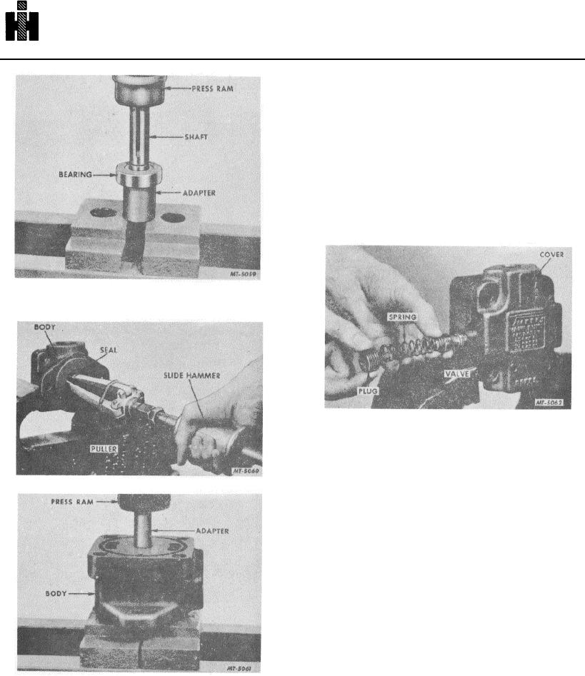
12. With a suitable adapter press out the inner
bearing from the body, Fig. 16.
13. Remove the plug and pull out the screen (see
insert Fig. 5). Do not remove the orifice plug
unless it is necessary.
14. Check whether there is a plug at each End of the
relief valve bore in the cover. If the bore is blind,
remove the plug and snap ring to release the
valve and spring as shown in the insert in Fig. 5.
If the bore is through the cover, remove only the
one plug to release the spring and valve, Fig. 17.
Leave the snap ring and the other plug in the
cover.
Fig. 14
11. Using puller SE-1961 remove shaft seal from
body, Fig. 15.
Fig. 17
INSPECTION AND REPAIR
Discard the used shaft seal and all "O" rings. Wash the
metal parts in mineral oil solvent, blow them dry with
compressed air and place them on a clean surface for
Fig. 15 Removing Shaft Seal Using Puller SE-1961.
inspection.
Check the wearing surfaces of the body, pressure plate,
ring and rotor for scoring and excessive wear. Remove
light score marks by lapping. Replace any heavily scored
or badly worn parts.
Inspect the vanes for burrs, wear and excessive play in
the rotor slots. Replace the rotor if the slots are worn.
Check the bearings for wear and looseness.
Rotate the bearings while applying pressure to check for
pitted or cracked races. Inspect the oil seal mating
surface on the shaft for scoring or wear. If marks on the
shaft cannot be removed by light polishing,
Fig. 16
629