
TRUCK SERVICE MANUAL
STEERING
Key
Description
Key
Description
1.
Button, Horn
19.
Bearing, Jacket Tube Lower Assy.
2.
Contact Cup, Horn Button
20.
Seat, Bearing
3.
Plate, Horn Button Contact
21.
Spring, Jacket Tube Bearing
4.
Spring, Horn Button
22.
Cap, Dust
5.
Nut, Steering Wheel Mtg.
23.
Cover, Universal Joint
6.
Wheel, Steering Assy.
24.
Bracket, Steering Column Mtg.
7.
Contact Ring, Horn Button
25.
Brace, Steering Column
8.
Contact Roller w/Cable
26.
*Yoke, Upper End
9.
Flange Steering Column w/Bearing
27.
Universal Joint
10.
Nut, Lock
28.
Fitting Lubrication 1/4 Straight
11.
Washer, Flat
29.
Slip Yoke
12.
Bolt, Clamp
30.
Seal, Slip Yoke
13.
Spacer, Bearing
31.
Shaft, Steering Slip
14.
Seat, Bearing
32.
Washer, Slip Yoke Seal
15.
Bearing, Jacket Tube Upper Assy.
33.
Cap, Dust
16.
*Shaft, Steering
34.
Yoke, Lower End
17.
Tube, Jacket
35.
Universal Joint
18.
Bracket Cap, Steering Column
36.
Yoke, Steering Gear End.
* Parts 16 and 26 welded together on late model chassis.
DESCRIPTION
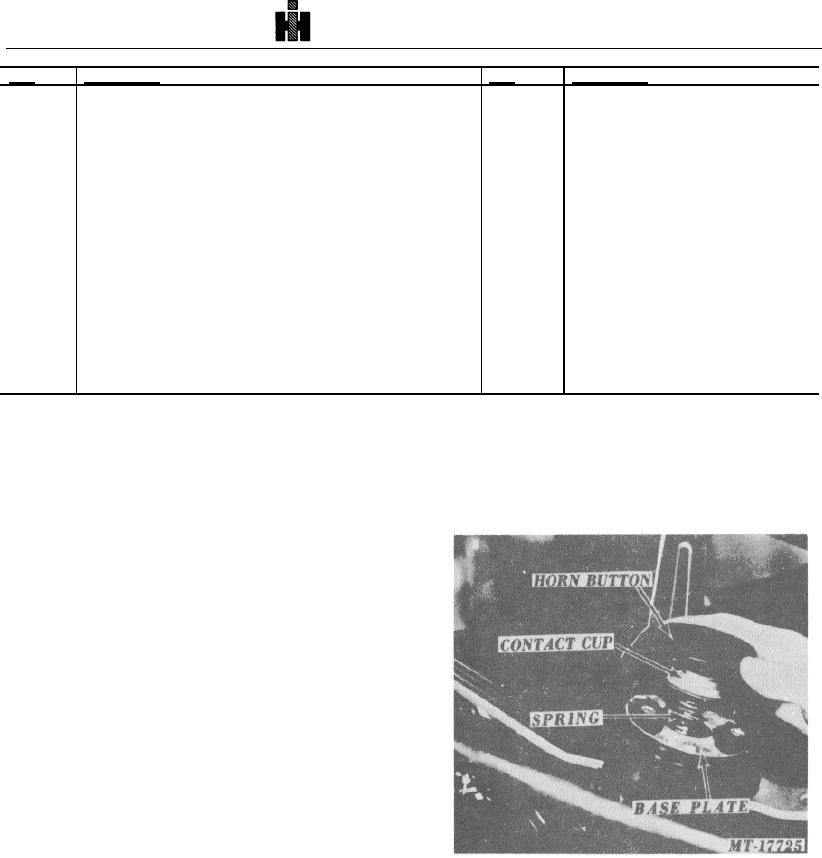
it 28.575 mm (1 1/8") in either direction. The horn button
The steering column assembly provides the
will be released from the rubber retainers on the horn
vehicle operator control of the steering gear from inside
button base plate. The contact cup and spring should
vehicle cab. This manual covers the 21 mm (7/81")
also be removed at this time (Fig. 2).
diameter shaft, double jointed column used in the
Transtar 4200, 4300, and 5000 Paystar series.
The turn signal and in most cases the trailer
brake control is mounted to the steering column jacket
tube. The only internal accessory not having to do
directly with control of the steering gear is the horn
assembly.
OPERATION
A steering wheel is connected to the upper
steering shaft, which is held by two sets of ball bearings
in the steering column jacket tube. The steering shaft is
connected to the slip shaft by a universal joint. The
lower end of the slip shaft is connected to the steering
gear by a second universal joint. The universal joints
and slip shaft permit correct alignment and smooth
rotation of the steering shaft to steering gear with no
Fig .
2 Plastic Horn Button Removal
binding of the shafts.
STEERING WHEEL REMOVAL
2.
Remove the horn button base plate by removing
three top screws and one "ground" screw.
The steering wheel can be removed as follows:
1.
Remove the plastic horn button by turning
656