TRUCK SERVICE MANUAL
TRANSMISSION
ASSEMBLY
Para 7-7
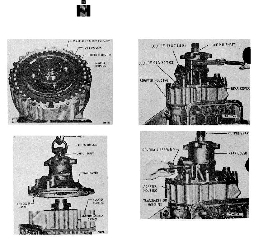
Fig. 7-19. Low planetary carrier, ring gear and clutch
Fig. 7.21. Installing rear cover bolts
Fig. 7-22. Installing governor assembly
(4) Install twenty-one 1/2-13 x 5 3/4inch bolts
and three 1/2 -13 x 7 1/4-inch bolts, and washers, to
Fig. 7 .20. Installing rear housing
retain the rear cover (fig. 7-21). Tighten the bolts to 67
(2) Place the rear cover gasket onto the rear
to 80 pound feet (90 to 108 Nm) torque.
cover. Retain the gasket with oil soluble grease (fig. 7-
20). Be sure the holes in the gasket are aliened with
(5) Install the governor assembly into the rear
those in the adapter housing.
cover by rotating it counterclockwise (fig. 7-22).
(3) Attach a lifting bracket to the output shaft
(6) Install the governor cover gasket and
(fig. 7-20). Using a hoist, guide the cover onto the
cover, and retain them with four 5/1618 x 9/16-inch bolts.
adapter housing. Since the two dowel pins in the cover
Tighten the bolts to 10 to 13 pound feet (14 to 17 Nm)
are of different size, simplification of installation is
achieved.
780

