
TRUCK SERVICE MANUAL
TRANSMISSION
HT 700D SERIES TRANSM ISSION
Para 7-4
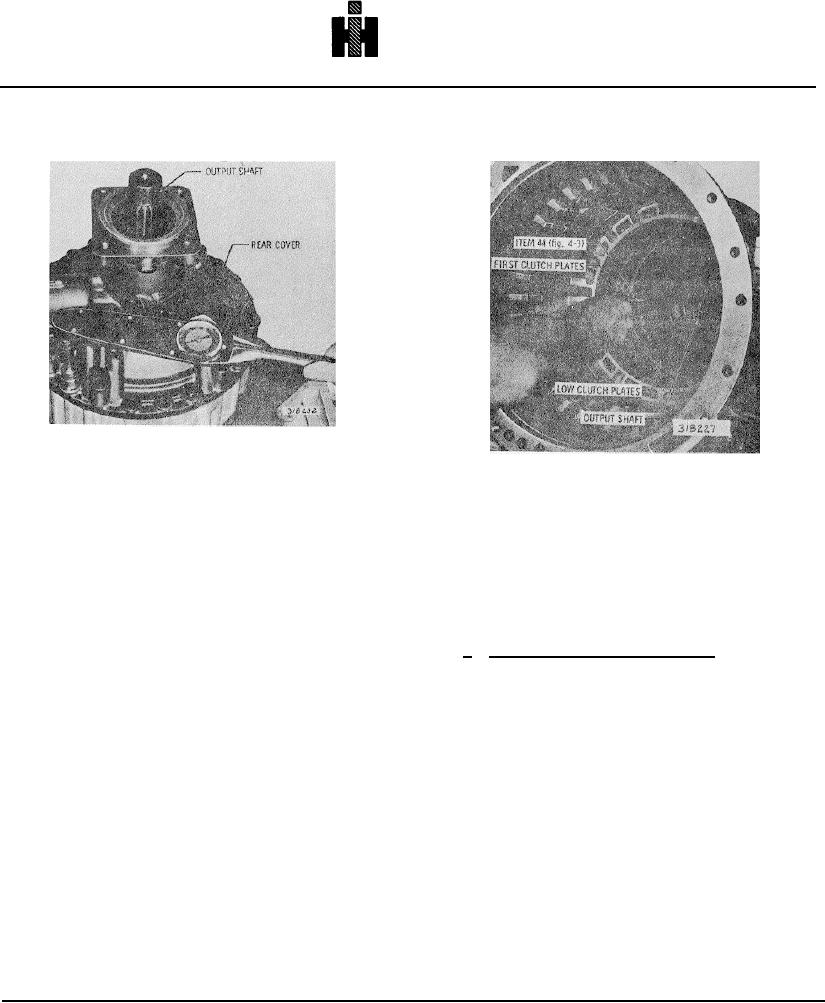
Fig. 7-9. Installing rear cover assembly
Fig. 7.10. Checking low clutch clearance
(4)
Beginning with an external-
tanged clutch plate, alternately install seven external-
to 3.68 mm). Any dimension within 0.095 to 0.145 inch
tanged and six internal-splined low clutch plates (refer to
(2. 41 to 3.68 mm) is satisfactory. However, the closer
Fig. 7-19).
the clearance is to 0.095 inch, the longer the interval
between clutch plate replacements will be. Clearance
(5) Install the rear cover assembly (as
must not be less than 0.095 inch. Replace worn clutch
assembled in para 6-22) and gasket onto the rear of the
plates with new plates to establish the desired clearance.
transmission housing and secure it with six 1/2-13 bolts
Recheck the clearance as described above.
and flatwashers, evenly spaced (Fig. 7-9). Tighten the
bolts to approximately 30 pound feet (41 Nm) torque.
b. Selecting Center Support Slapring
(6) Invert the transmission, front end upward.
(1) Install thirteen second clutch plate s,
Using gage 44 (Fig. 4-3), check the clearance between
beginning with an external-tanged plate. Alternately
the low clutch plates (fig. 7-10). It is recommended the
install seven external tanged plates and six internal-
gage be placed between the adapter housing wall and
splined plates (Fig. 7-3).
the first steelplate. The prescribed running clearance is
0.095 to 0.145 inch (2. 41 to 3.68 mm) Any dimension
(2) Install the clutch plate retaining snapring
within 0.095 to 0.145 inch (2.41 to 3.68 mm) is
(Fig. 7-4). Be sure the snapring gap is at the top of the
satisfactory. However, the closer the clearance is to
transmission housing.
0.095 inch, the longer the interval between clutch plate
replacements will be. Clearance must not be less than
(3) Remove the third-clutch piston from the
0.095 inch. Replace worn clutch plates with new plates
center support assembly (if not previously removed).
to establish the desired clearance.
Recheck the
Install bracket 5 (Fig. 4-2) into the recess between the
clearance as described above.
step-joint sealrings on the center, support hub (Fig. 7-5).
(7) Using gage 44 (Fig. 4-3), check the
(4) Install the center support into the
clearance between the first clutch plates (Fig. 7-11). It is
transmission housing (Fig. 7-5). Be sure the
recommended the gage be placed between the
transmission housing and the first steel plate. The
prescribed running clearance is 0.095 to 0.145 inch (2.41
775