TRUCK SERVICE MANUAL
TRANSMISSION
HT 700D SERIES TRANSMISSIONS
Para 6-34/6-35
(4) Install the remaining pinion groups and
pins in the manner described above.
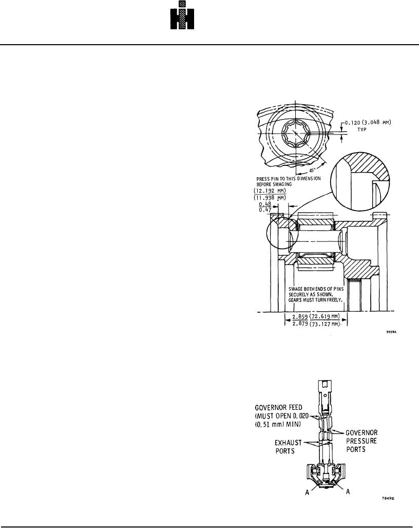
(5) Support each pinion pin on a.0. 812inch
(20. 62 mm) (approx.) anvil. Using a suitable punch,
swage the ends of each pinion pin firmly against the
carrier, to form the pattern shown in figure 6-72. After
swaging, each pinion must rotate freely, with 0. 008 to 0.
031inch (0. 20 to 0.78 mm) end play.
6-35. GOVERNOR INSPECTION
a. Inspect the governor to determine that its
function has not been impaired. If dirt or other foreign
materials are present, clean the governor in mineral
spirits then check the governor as explained in c, below.
If the governor function is still impaired, disassemble the
governor as explained in b, below.
b. Remove pins 'A' shown in figure 6-73 and
carefully remove the governor weights and springs.
Slide the governor valve out of its housing and after
cleaning the valve and housing, check for wear. If wear
is evident, replace the governor, otherwise assemble the
governor by reversing the disassembly procedure above.
Be sure the governor valve is installed as shown in figure
6-73. New pins must be used at reassembly. These
pins, with instructions, are available in kit form. See your
HT 700 Series parts catalog SA 1268 for detail part
number.
Fig. 6-72. Components of rear planetary carrier
assembly 771
c. Hold the governor assembly drive gear upward,
as shown in figure 6-73. Hold one weight outward
against its stop. Check the opening at the governor feed
port. This is the distance the governor valve land clears
the bottom side of the port. Repeat this check while
holding the other weight outward against the stop. The
minimum opening should be 0.020 inch (0.51 mm). If
the opening is less, replace the governor.
Fig. 6-73. Governor assembly-showing port openings
771

