
TRUCK SERVICE MANUAL
TRANSMISSION
INSPECTION AND REBUILD
Para 6-32 -34
pin 46 until the swaged end is sufficiently weakened.
CAUTION
Do not drill into metal of carrier 40.
(3) Place carrier assembly 38 in a press, and
press four pins 46 from carrier 40, shearing the drilled
ends of pins 46.
(4) Remove, as a unit, each of the four pinion
groups consisting of pinions 43, thrust washers 42 and
45, and needle roller bearings 44.
NOTE
Refer to paragraph 6-2, above.
b. Assembly (A, foldout 13)
NOTE
To facilitate assembly, it is permissible
to freeze pinion pin 46 or heat carrier 40
before pinion pin installation.
(1) Install a needle roller bearing 44 into the
bore of each pinion 43. Place a steel thrust washer 45
(first) and a bronze thrust washer 42 (second) onto each
face of pinions 43.
Fig. 6.69 Components of center planetary carrier
assembly
(2) Position carrier 40, front downward
(bushing bore upward), in a press. Place a pinion group
6-34. REAR PLANETARY CARRIER
(as assembled in (1), above) into the carrier. Align the
ASSEMBLY
pinion group with the pinion pin bore in the carrier.
NOTE
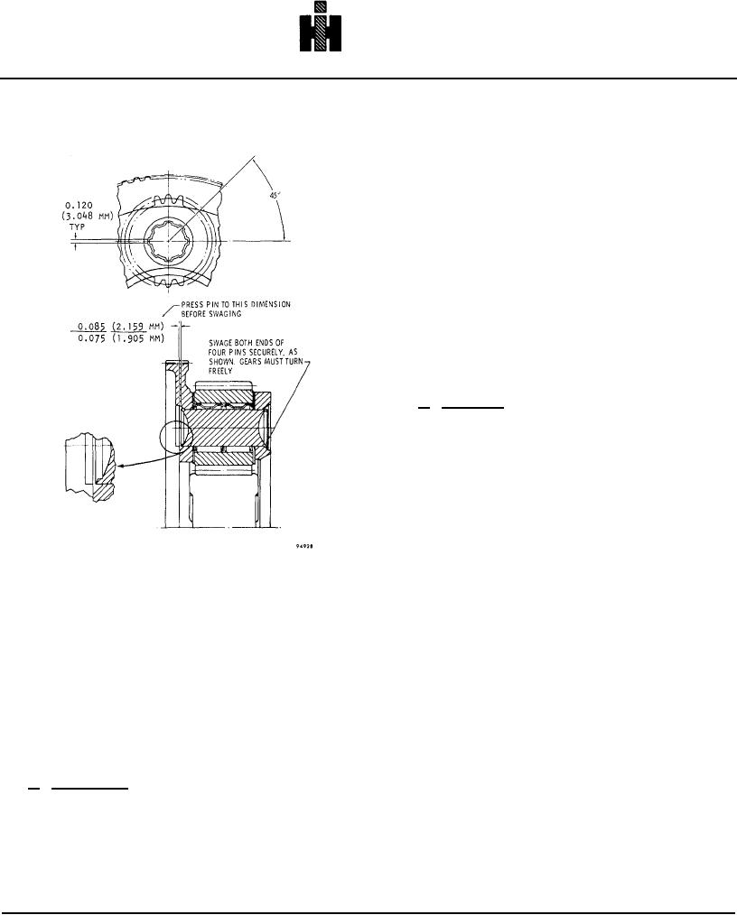
(3) Install a pinion pin 46, and press it through
Disassemble the planetary assembly
the carrier and pinion group, to the dimension shown in
only if there is evidence of undue wear
figure 6-72.
or damage.
Failure of one pinion
requires the replacement of the entire
NOTE
set, because the pinions are selectively
Pins must be a tight, to moderately tight,
matched.
press fit (when parts are at normal
temperatures).
a. Disassembly (A, foldout 13)
(1) If carrier 40 or bushing 41 is damaged or
otherwise unserviceable, replace with a carrier and
bushing assembly. Field replacement of the bushing
alone is not recommended.
(2) Using
a31/32-inch
drill,
centered
accurately, drill into one end of each pinion
770