
TRUCK SERVICE MANUAL
TRANSMISSION
Para 7-1/7-3
Section 7. ASSEMBLY OF TRANSMISSION
FROM SUBASSEMBLIES
7-1. SCOPE OF SECTION 7
from the thicknesses of corresponding plates in later
models. Wear limits started in Section 8 are for plates
This section covers the assembly of the
presently supplied.
transmission. It is arranged in a continuous sequence to
facilitate assembly. Certain illustrations will not always
(3) If it is necessary to replace an external-
illustrate the model being assembled, but, when the
tanged plate, be sure the plate thickness is identical to
operation is identical, the illustration may be referenced
the original equipment. Refer to b(l) and (2), above.
and will correctly illustrate the procedure.
Keep the clutch plates separated; do not mix the plates
of one clutch with the plates of another.
7-2. CLUTCH CLEARANCES
(4) Clearance for the third clutch is
a. Preparation Procedure.
Preparations are
established during assembly. Clearances for the forward
required to establish the proper running clearance for
and fourth clutches are established during rebuild of
each clutch pack. Follow the procedures in b, below.
those subassemblies in Section 60
b. Determine Plate Thickness
(1) Determine the original thickness of each
external-tanged plate with a micrometer. Because the
tangs of the clutch plate are not subject to face wear, the
micrometer reading at a tang will be the original
thickness. Note that each clutch pack must contain one
thick plate next to the piston, and a basic number of thick
and thin plates. The combination of thick and thin plates
are selected to meet the prescribed clearance with the
clutch released. Install all thick plates toward the piston
end of the pack.
(2) Determine the wear on both internal and
external plates (refer to wear limits in Section 8).
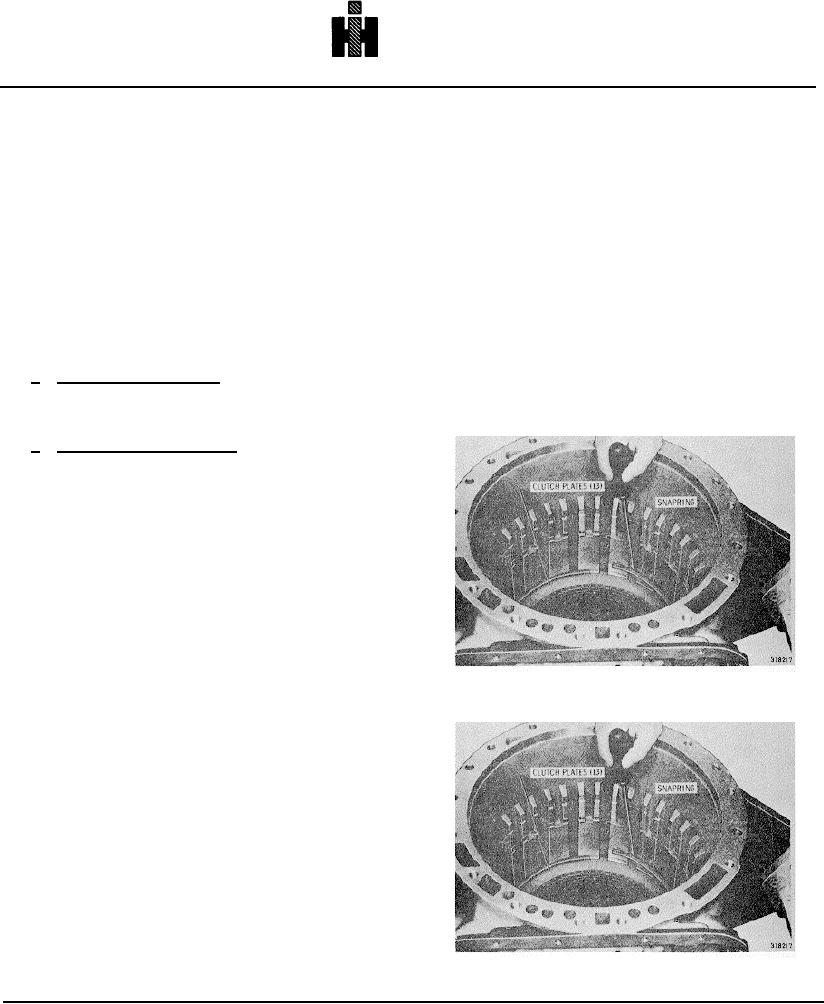
Fig. 7-3. Installing second clutch, external-tangled plate
Replace worn plates. Note that the thicknesses of
external-tanged plates in the low, first, second, and third
clutches in earlier models may be different
Fig. 7-4. Installing second clutch snapring
773