
TRUCK SERVICE MANUAL
TRANSMISSION
HT 700D SERIES TRANSMISSION
Para 7-6
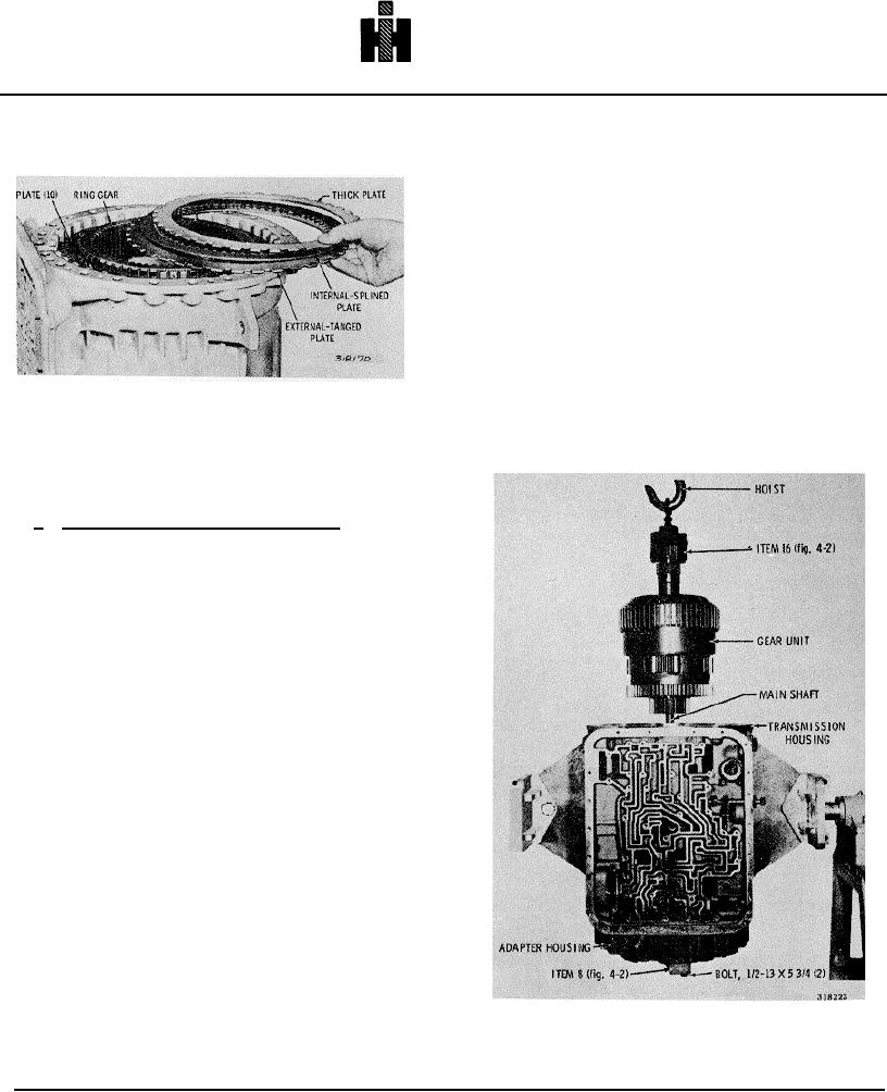
(5) Install compressor bar 8 (Fig. 4-2) onto the
adapter housing. Retain it with two 1/2-13 x 5 3/4-inch
bolts (Fig. 7-14).
(6) Position the transmission with the front
end upward.
(7) Remove the center support snapring and
anchor bolt. Attach bracket 5 (Fig. 4-2) to the center
support, and remove the support assembly (Fig. 7-5).
(8) Remove the snapring and the second
clutch plates (Fig. 7-4). These plates are now preset for
Fig. 7-12. Installing first clutch plates
proper clearance and should be retained as a pack for
final installation.
7-6. INSTALLING FIRST CLUTCH, GEAR UNIT,
SECOND CLUTCH, CENTER SUPPORT
a. First Clutch, Rear Planetary Ring Gear
(1) Place the rear planetary ring gear, short
splines (rear) downward, on a bench. Install ten of the
plates from the clutch pack removed in 7-4c(5), above,
as follows. Lay aside the first three plates from the
piston end of the pack (refer to para 7-2b). Starting with
the fourth plate in the pack (internal splined), alternately
install five internal splined and five external tanged plates
onto the ring gear.
(2) Align the external tangs of the plate pack.
Carefully invert the ring gear and plate pack, and install
the assembled parts into the rear of the transmission
housing.
(3) Install the three remaining plates of the
pack (external-tanged, internal-splined, external-tanged
sequence).
NOTE
Last plate installed must be a thick plate.
(4) Place the adapter housing with piston
(front) downward onto the transmission housing.
Fig. 7-14. Installing gear unit assembly
777