
TM 5-3805-274-13&P
0043
REMOVAL
NOTE
Have a suitable container that holds up to 27 gal. (102 L) ready to
catch oil.
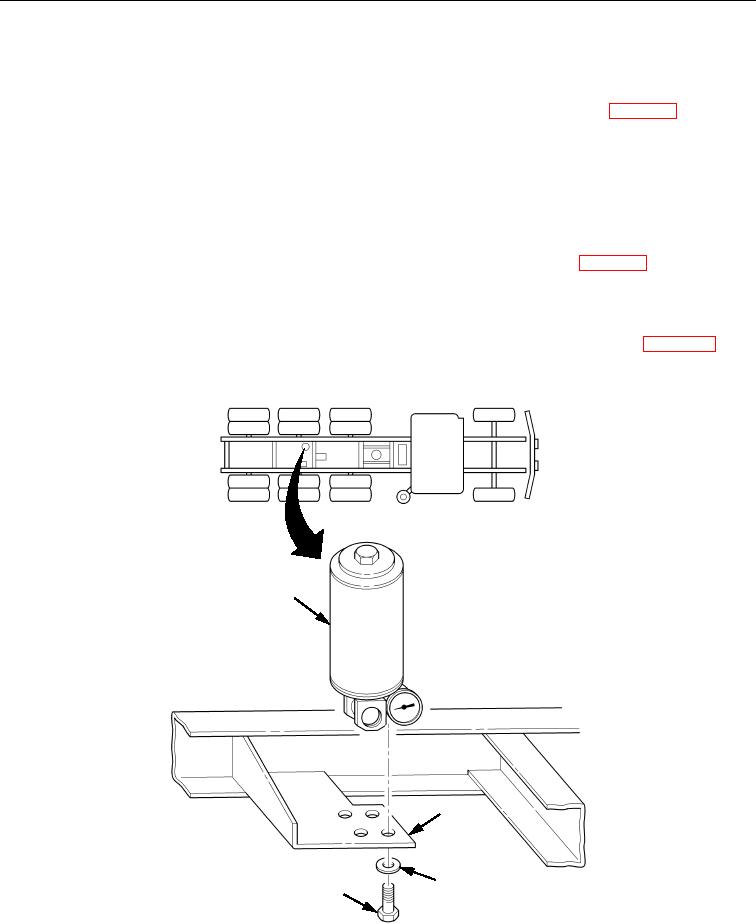
1. Remove hydraulic lines and fittings from filter assembly (Figure 1, Item 1), refer to WP 0040.
2. Remove four bolts (Figure 1, Item 4), lockwashers (Figure 1, Item 3), and filter assembly
(Figure 1, Item 1) from support brace (Figure 1, Item 2). Discard lockwashers (Figure 1, Item 3).
END OF TASK
INSTALLATION
1. Install filter assembly (Figure 1, Item 1) on support brace (Figure 1, Item 2) with four new lockwashers
(Figure 1, Item 3) and bolts (Figure 1, Item 4).
2. Install hydraulic lines and fittings on filter assembly (Figure 1, Item 1), refer to WP 0040.
3. Remove filler cap from hydraulic reservoir tank and fill hydraulic reservoir tank to center of bottom sight
glass indicators.
4. Start engine and engage PTO (TM 9-2320-273-10). Check for oil leaks, raise dump body bed, lower
safety strut from locked position to stowed position on subframe, lower dump body bed (WP 0008),
recheck oil level at top sight glass indicators, and shut down engine.
1
2
3
4
Figure 1. Filter Assembly Removal and Installation.
END OF TASK
END OF WORK PACKAGE