
AXLE-FRONT
TRUCK SERVICE MANUAL
(if removed) on chassis equipped with hydraulic brakes.
Clean and repack the front wheel bearing. Then
install the bearing in the hub assembly using new grease
seals, Assemble the hub and bearings on the spindle
being careful not to damage the oil seals or bearings.
Adjust wheel bearings referring to WHEEL BEARING
ADJUSTMENT. Then install wheel grease caps.
TIE ROD ENDS
The tie rods are of three-piece construction,
consisting of a tie rod and two rod end assemblies. The
ends are threaded to the rod and locked with clamp
bolts. Right and left hand threads are provided for toe-in
adjustment. Tension on ball stud in the rod ends are
self-adjusting and require no attention in service other
Fig. 14
than periodic inspection to see that the ball studs are
tight in the steering knuckle arms.
7. Align flat (or flats) to mate with draw key hole (or
holes). Drive knuckle pin through knuckle yoke,
Fittings are provided for periodic lubrication on
axle center and thrust bearing from top or
some types of tie rod ends. Where no fittings are used,
bottom side.
the tie rods have been lubricated at assemble and no
further lubrication is necessary.
8. Install the draw key (or keys). Drive the draw
key with flat side positioned to mate with flat on
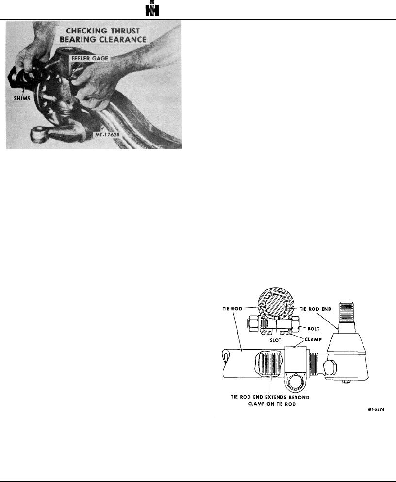
CAUTION: When tie rod, drag link or power
knuckle pin. Tighten nut to the specified torque.
steering linkage ends are replaced they must be
threaded into the tie rod sufficiently so that when the
EXPANSION PLUGS
clamp is applied, the clamping action will be directly over
1. On axles that have grooved holes, install lock
the threads on the ball joint end. Be sure that the end is
rings.
in far enough (past the clamp) to provide adequate
clamping and the bolt in the clamp is installed next to
2. On axles not grooved for lock rings, install
(over) the slot in the tie rod as shown in Fig. 15.
grease retainer plate and secure in place by
staking in four equally spaced places.
3. On units employing grooved knuckle pins that
protrude below the knuckle lower yoke, install
lock ring in groove.
COVERS, CAPS OR RETAINERS WITH FELTS
1. Install the cover or cap and gasket with cap
screws where used.
2. Install the felt, retainer and lock ring on
protruding straight pins that are not provided with covers
or caps.
Reinstall the tie rod tapered ends into the
steering arms and tighten the nuts to the correct torque
specification Then install the cotter pin. (Refer to TIE
ROD ENDS for replacement of tie rod ends.)
Reinstall brake chambers, connecting the push
rods also. Reinstall hydraulic brake cylinder fluid adapter
fitting
18