
TRUCK SERVICE MANUAL
AXLE-REAR
(NEW GEARS)
Tooth contact may be checked by applying a thin even
coat of lightly oiled red lead with a small brush to both drive
and coast sides of a dozen teeth of the gear. When the pinion
is rotated the red lead is squeezed from the gear teeth by
pressure of the pinion teeth leaving areas the exact size,
shape and location of the contacts. Sharper, better defined
areas of contact can be obtained by applying rolling resistance
to the gear providing the gear is not forced out of location
during the checking operation.
Use the smallest amount of the lead and oil mixture that
will render good impressions. The drier the mixture the better
the impressions. Clean the material from the gear and pinion
teeth when the operation is complete. Always judge tooth
contact by noting pattern on the drive side of the gear teeth.
The coast side pattern should be correct when the drive side
pattern is correct.
3. While watching the indicator push inward on the
IMPORTANT: When backlash amount is not specified, set
flange or yoke and roll it back and forth until the
backlash to the following:
indicator stops changing. Make a note of this reading.
In a similar manner, pull outward and roll the flange or
STDD
yoke until the indicator again stops changing. The
Forward Rear -.005 to .015
difference between this reading and the inward
Rear Rear -.005 to .015 SUDD
reading is the adjustment condition.
Forward Rear -.005 to .015
Rear Rear -.020 to .026, however, .010 should be used
4. Correct to .003 to .005 end play if necessary by using
for establishing tooth contact pattern, than opened
thicker or thinner spacer.
to .020 to .026.
E. Remove yoke or flange and input nut.
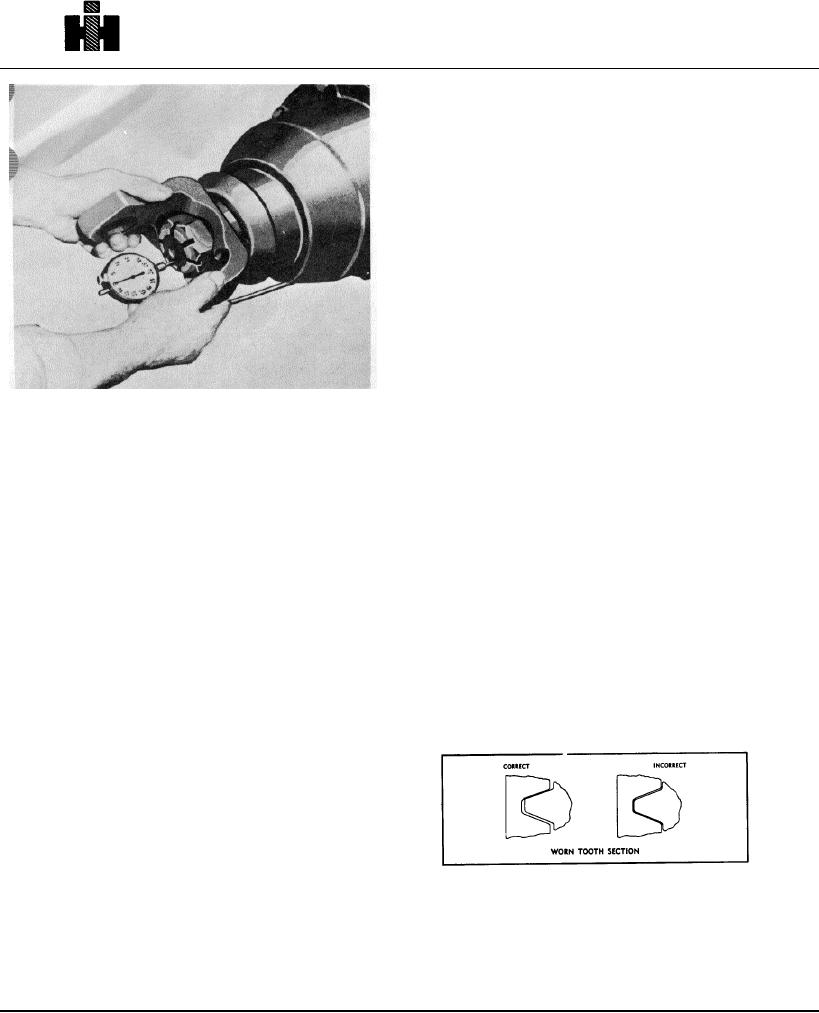
RE-CHECK BACKLASH (USED GEAR SETS)
F. Install oil slinger if used, reinstall yoke or flange, input
Generally, if original gears are being re-installed in
washer and nut. Tighten nut to recommended torque
assembly, red leading of teeth will not indicate the same
value.
contact as new gears and can be misleading. Gears that have
been in service for long periods form running contacts due to
SHIFT SHAFT ADJUSTMENT
wear of teeth. Therefore, the thickness of the original shim
pack plus approximately .015" additional shim stock should be
1. Apply air or vacuum to move shaft to its full travel to
maintained to check gear lash. In the event that gear lash is in
"lock" interaxle differential.
excess of maximum tolerance, as stated under gear
adjustment, reduce gear lash, only in the amount that will avoid
2. Turn adjusting screw (in rear of unit) to contact shift
overlap of the worn tooth section.
shaft.
3. After contact with shaft has been made turn adjusting
screw in 3/4 of a turn.
4. Lock adjusting screw in position with jam nut.
ESTABLISH TOOTH CONTACT AND GEAR
Gear lash can only be reduced to a point of maintaining
BACKLASH
smooth rotation of bevel gears.
Hypoid gear first reduction units have a single shim pack
Smoothness or roughness can be noted by rotating bevel
between the pinion cage and carrier or interaxle differential
gear. If a slight overlap, as illustrated, takes place at worn
housing and carrier to control pinion position.
tooth section, rotation will be rough. Generally with the original
A shim pack between the cross shaft bearing cage flange and
gears,
tone
should
be
satisfactory.
the carrier controls the position of the first reduction hypoid
gear in all top mounted double reduction drive units.
41