TRUCK GINE ICE MANUAL
EN SERV
2. Check guide for straightness. It should be at
right angles with milled surface of head. Mark guides for
replacement if not straight or worn beyond replacement
limit.
3. Check crossheads for cracks with Magnaglo
process.
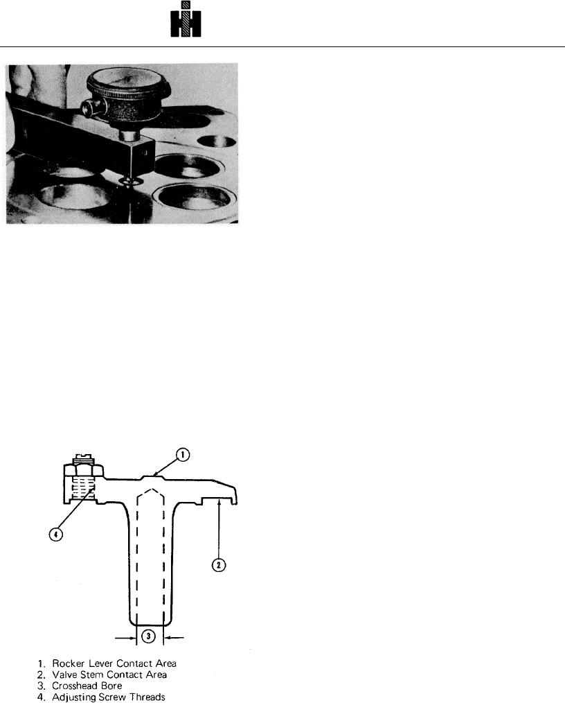
4. Check stem inside diameter (3, Fig. 2-6) using a
small bore gauge set at 0.4402 inch [11.181 mm]. Use
as a "No Go" gauge to check for wear beyond worn
replacement limit,
5. Check for out-of-round holes, gauge at several
points 90 deg. apart. Do not use plug gauge for this
operation.
6. Visually check for excessive wear on rocker
Fig. 2-5 (N 10206) Measure injector tip protrusion
lever (1) and valve stem contact surface (2). Check
adjusting screw and crosshead threads (4) for wear or
bottom of head surface. If indicated seat width does not
distortion. Mark for replacement If excessive wear is
meet these specifications, mark sleeve for replacement.
found.
Valve Guides
2. Install injector assembly, torque to 10 to 12 ft-lbs
1. Check guide inside diameter; using a small bore
[1.4 to 1.7 kg m]. Measure tip protrusion with ST-547
gauge set at 0.4552 inch [11.562 mm]. Use bore gauge
Dial Indicator, ST-981 Injector Tip Protrusion Checking
as a "No Go" gauge, Table 2-1 (3).
Tool or equivalent. Fig. 2-5. Tip protrusion must be
2. Check for out-of-round holes; gauge at several
0.060 to 0.070 inch [1.52 to 1.78 mm] . See Service Tool
points crosswise and endwise of head. Do not use a
Instructions.
plug gauge for this operation. Visually check valve
guides for chips, cracks or burrs. Mark for replacement
any guides showing excessive wear or damage.
Valve Crosshead Guides And Crossheads
Valves
1. Check guide outside diameter with micrometers.
Visual
See Table 2-1 (6) for worn replacement limits.
Clean valves with a buffer and polish with crocus cloth.
Inspect. then discard if:
Heads are cupped, cracked, pitted or worn too thin to
regrind within limits. Check valve head rim thickness (A,
Fig. 2-7), it should be a minimum of 0.105 inch [2.67
mm]. Stems are worn beyond worn replacement limit as
listed in Table 2-1 (2). Collet recesses are worn so new
collets will not fit securely in recesses.
Magnetic Method
1. Surface to be inspected must be cleaned to
remove all foreign material which could give false
indications or react in any way with penetrant or
developer. Vapor degreasing is recommended.
2. Welded valves which have two types of metal,
may be Magnaglo inspected. However, due to change of
metal at weld, there will be magnetic leakage at this
point. This will be indicated by a broad fuzzy pattern of
magnetic particles. For this reason, such valves should
be magnetized in coil at
Fig.2-6. (V40236) Crosshead wearpoints
355

