
TRUCK SERVICE MANUAL
ENGINE
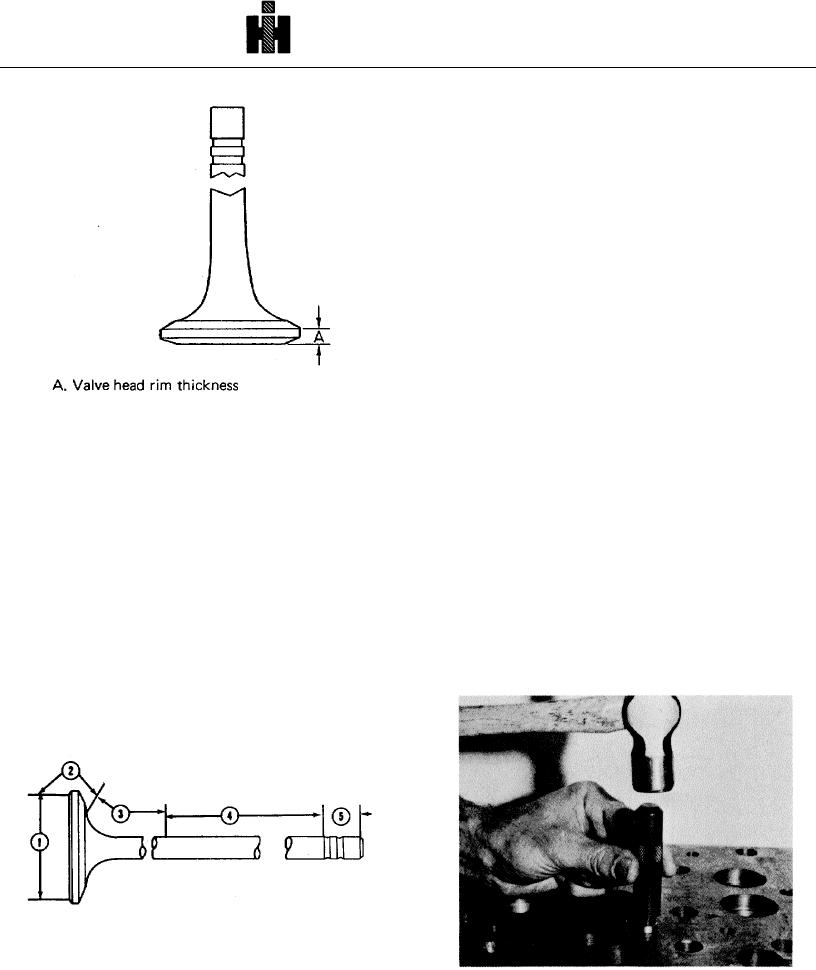
a. No magnetic indication over 1/2 inch [12.70 mm]
in length or more than 5 indications spaced closer than
1/8 inch [3.18 mm] can be accepted in area (1).
b. No visible or magnetic indication acceptable in
area (2).
c. No visible or circumferential magnetic indications
are acceptable in areas (3) and (4).
d. No visible or magnetic indication is acceptable in
area (5).
Note: "Visible" means indication can be seen by use of
a 3 power magnifying glass after removing magnetic
particle suspension.
5. Demagnetize all acceptable parts.
Fig. 2-7 (N10231) Minimum valve head rim thickness
REBUILDING
low amperage, at 100 to 200 amps, and then inspected
Sleeve Eroded Water Holes
residually with Magnaglo. A crack at, or near, the weld
would show as a sharp bright fluorescent line.
Cylinder head surface around water holes must be free
of any erosion, pits, scratches or blemishes which are
more than 0.003 inch [0.08 mm] deep in the area 1/16 to
3.
Valves with only one type of metal can be
5/32 inch [1.59 to 3.97 mm] from edge of water hole.
inspected in normal way. Magnetize and inspect in two
Use ST-1010 Water Hole Counterboring Tool to enlarge
directions. Coil magnetization, use 100 to 300 amps.
hole for sleeve. See Service Tool Instructions.
Inspect with residual Magnaglo. Defects found after this
magnetization will be in a transverse direction. Follow by
1. Coat sleeve, Part No. 191078, (1, Fig. 2-9) with
headshot magnetization, at 500 to 700 amps, use
sealant, align sleeve in top of water passage hole, drive
residual Magnaglo. Defects by this magnetizing method
into position using bushing driver (2) and hammer.
will be radial.
4. Magnetic indications should be as follows:
Reference Fig. 2-8.
Fig. 2-8 (N10269) Magnetic indication areas of
maegnaglo
1. Sleeve
2 Bushing Driver
Fig. 2-9 (N10264) Drive bushing into hole
356