TRUCK SERVICE MANUAL
ENGINE
should not require lapping to effect an air-tight seal;
8. Use ST-884 Injector Sleeve Cutter in a drill press
however, a small amount of lapping is permissible if
with pilot, using a solid stream of good cutting oil to allow
necessary in order to pass Valve Seating (vacuum) Test.
cutter to cut freely without grabbing, etc.
Valve Springs
9. Water test cylinder head. See Page 2-4.
Weak valve springs may cause valve flutter resulting in
Grind Valves
excessive wear on both valve and seat. Valve flutter
1. Check valve grinder setting by using a new valve
interferes with valve timing and may cause valve to strike
and an indicator gauge:
top of piston.
a. Check valve in valve grinder on guide area of
1. Test valve spring on spring tester that is capable
stem. Relieved portions on both ends of guide area are
of accurate measurement of valve springs length, apply
not necessarily concentric to guide area of stem.
required load for length as listed in Table 2-1 (9). If valve
springs compress to dimensions shown, at less than
b. Indicate on ground face of valve.
load indicated under "worn-limit", discard valve spring.
c. Turn valve and mark high spot on head of valve.
2. Spacers should be used under valve spring
d. Rechuck valve 180 deg. from first position.
when insert and valve have been refaced more than a
e. Repeat (b) and (c). If high spots are same for
total of 0.030 inch [0.76 mm]. A maximum of two (2)
Part No. 68803-A spacers may be used under valve
both (a) and (d) position, valve is warped. If high spots
springs.
occur in different positions, chuck is out of alignment.
Runout should not exceed 0.001 inch [0.03 mm].
ASSEMBLY
2. Wet-grind valves to an exact 30 dep. angle from
1. Install pipe plugs and fuse plug using sealant or
horizontal. Check rim thickness as shown in Fig. 2-7. If
sealing tape. Torque plugs to values listed in Table 2-1
rim is less than 0.105 inch [2.67 mm], valve is not
(10).
suitable for reuse.
Note: Cylinder heads contain breather or vent holes that
3. Pencil mark valve face as shown in Fig. 2-12,
must be "plugged" on turbocharged engines and "open"
position in valve guide against a newly ground valve
on naturally aspirated engines. Vent holes are located
seat, rotate valve 10 deg. A good seat will be indicated if
above air, intake port on cylinder head.
all pencil marks are broken. If pencil marks are not
2. Dip valve stems into clean engine lubricating oil,
broken, tools need dressing or machine has not been
insert into valve guides. Place cylinder head face down
properly adjusted; final check should be made with a
on wooden bench or protective surface to prevent
vacuum tester.
marring finish surface.
4. Valve seats properly ground with precision
3. Place lower valve spring guides over valve
equipment
guides.
CAUTION
See current Parts Catalog for correct spring and guide
combination, certain valve springs and spring guides
must not be mixed under a given crosshead.
4. Install intake valve guide seals (if used). Valve
guide seals are not currently being used on factory built
engines. It is recommended seals be removed from
engines using them unless it is desired to continue use
of valve guide seals. Valve guides need not be changed
if seals are removed.
5. Assemble springs, spring seats, and spring
spacers as required. Place upper valve spring retainer
over springs, compress with ST-448 Valve Spring
Compressor, install new half-collets.
Valve Seating Test
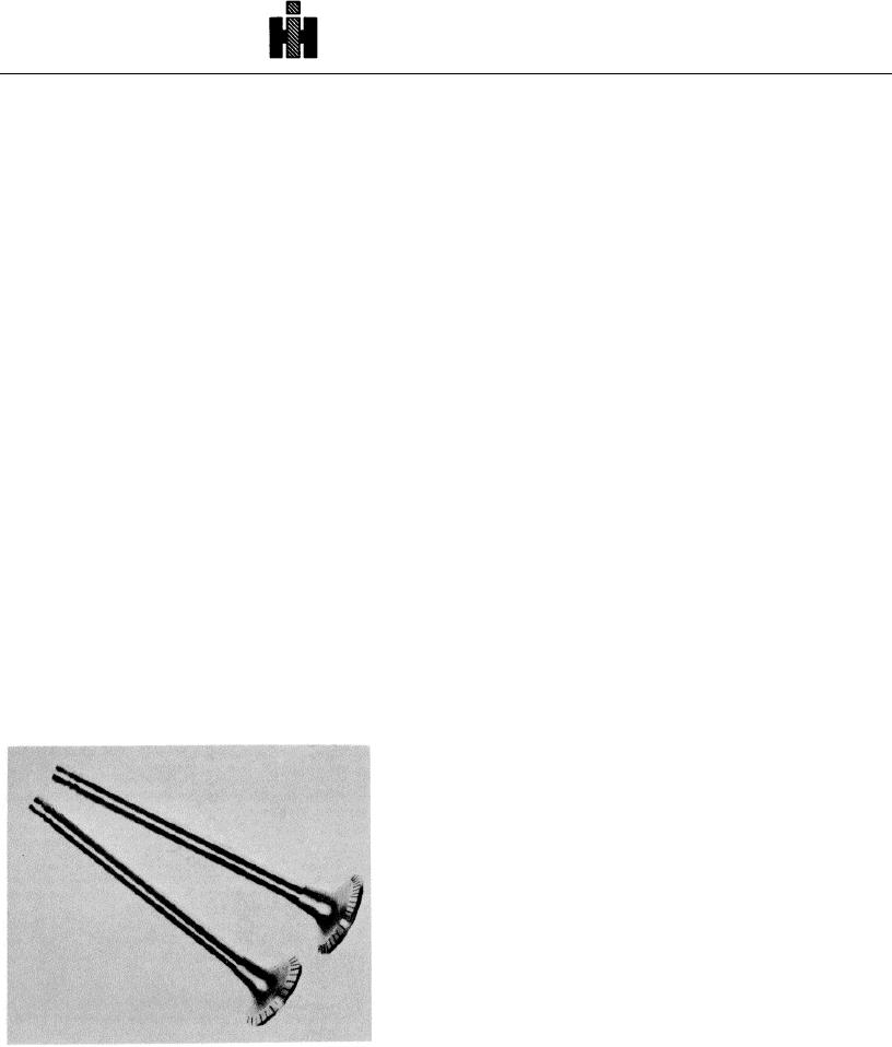
Fig.4 21 (N201Pencil marks on valves
Vacuum testers are available to check valves and seats
for leakage. ST-417 Tester for 6 volt system, ST-417-A
Tester for 12 volt system and ST-1257 for 110 volt AC
system. The systems consist of vacuum pump, vacuum
gauge and vacuum cups.
359

