TRUCK SERVICE MANUAL
ENGINE
Service Tools (Or Equivalent) Required
Service
Tool
Tool Number
Name
ST-691
Mandrel and Block
ST-863
Mandrel
ST- 1053
Driver
ST-1182
Alignment Tool (80 deg.
Tilt engine)
Standard Tools - Obtain Locally
Small Bore Gauge
Micrometers (1 to 2 inch)
Radius Gauge (1/4 inch
[6.35 mm])
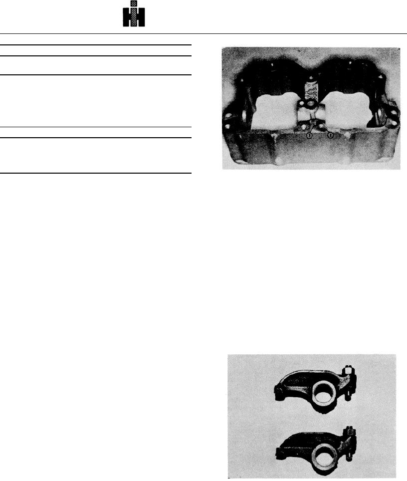
1. Vent Hole
2. Oil Drilling
ROCKER LEVER HOUSING
Fig. 3-2, (N 10318). Breather hole location
DISASSEMBLY AND INSPECTION
ROCKER LEVERS
1. Tag rocker levers for position, as removed and
INSPECTION AND REPAIR
remove adjusting screws and nuts from all levers.
1. Check for surface imperfections by magnetic
2. Remove setscrew or spray nozzle and jam nut
inspection. Apply coil magnetization, amperage at 300 to
(80 deg. tilt engines) positioning rocker lever shaft in
500 with residual Magnaglo. See Fig. 3-3 for most
housing.
likely areas. Demagnetize after checking.
3. Drive a sharp pointed punch through plug at end
2. The ball end of rocker lever adjusting screw
of rocker shaft. Pry out concave type plug or press
must be a true sphere. Check with 1/4 inch [6.35 mm]
through housing if cup type. Use a flat or drift punch to
radius gauge. Replace if flat at bottom or there is
drive or press shaft through housing.
evidence of scratching or galling.
Check thread
condition on all screws and in levers. Check closely for
4. Locate shaft in V-block, not a vise and remove
threaded distortion at assembly position of locknut.
plugs.
Screws must run freely through levers.
5. Visually inspect all capscrew holes for damaged
threads and inspect all levers, housings and covers for
cracks, chips or breaks
6. Inspect entrance of shaft bore for sharp edges,
nicks or burrs when cup plugs are used, entrance of bore
should have a slight radius. Sharp edges can be
removed by using 240 grit aluminum oxide paper over a
split rod, rotating in an electric drill.
7. Check breather vent hole (1, Fig. 3-2) and
rocker lever oil drilling (2) to make sure they are free of
dirt or other deposits.
8.
Check rocker lever shaft bore of housing
inside diameter. Dimensions should be 1.1238 to 1.1246
Fig. 3-3, (V40305). Magnetic inspection crack indication
inch [28.545 to 28.565 mm] . If shaft bore does not meet
these dimensions. discard housing and replace. See
Parts Catalog for correct part number.
363

