
TRUCK SERVICE MANUAL
ENGINE
3. Use ST-663 Valve Guide Arbor and ST-257
Sleeve Installation
Valve Seat Insert Tool Driver, Fig. 2-10, to hold and
1. Coat new "0" rings with clean engine lubricating
drive ST-662 Valve Seat Insert Cutter when cutting valve
oil. Install "O" ring into groove of head injector sleeve
seat insert counterbore.
bore.
4. Cut counterbore 0.006 to 0.010 inch [0.15 to
2. Using ST-1227 or equivalent Injector Sleeve
0.25 mm] deeper than insert thickness to permit staking
Installation Mandrel, push new injector sleeve into bore
or peening of head to hold insert. Allow cutter to dwell
of cylinder head until it bottoms. Do not strike mandrel
upon reaching proper depth to insure a flat seating
with hammer during this step. Remove mandrel.
surface.
3. Install ST-1179 Injector Sleeve Holding Tool.
5. Install valve seat insert and stake insert in head
Tighten nut to 35 to 40 ft-lbs [4.8 to 5.5 kg m] torque.
using ST-1122 Tool Driver over shaft of ST-1124 Insert
4. Insert mandrel into sleeve bore, strike mandrel
Staking Tool. A 1/4 inch [6.35 mm] diameter round end
two moderate blows with hammer to insure that Injector
punch may be used if staking tool is not available.
sleeve is properly seated. Retighten injector sleeve
CAUTION
holding tool to 35 to 40 ft-lbs [4.8 to 5.5 kg m] torque.
Over-swaging around insert may crack cylinder head.
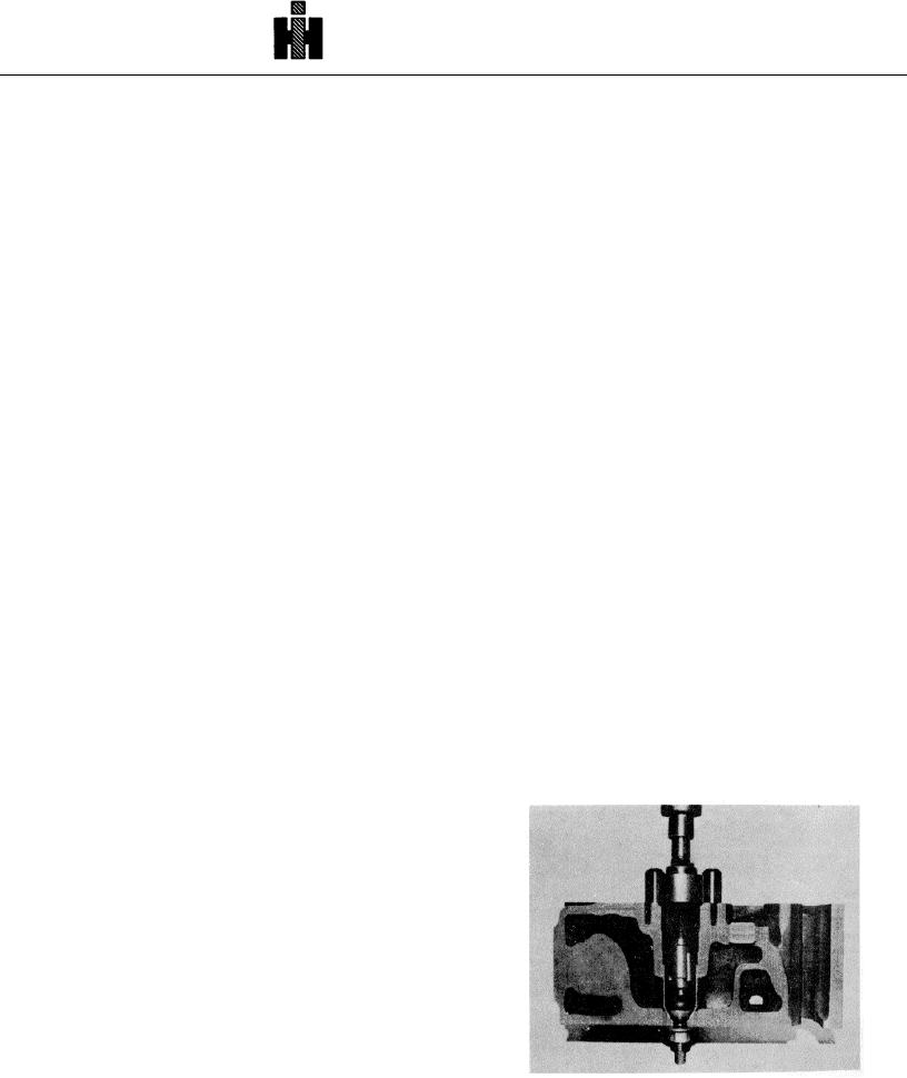
5. Roll top 1/2 Inch [12.70 mm] area of sleeve with
ST-880 Expanding Roller. Fig. 2-11. Use inch-lb [kg m]
Grind Valve Seats
torque wrench to turn ST-880; turn mandrel until a 75
1. Use ST-685 Valve Seat Grinder and correct
inch-lb [0.9 kg m] maximum torque reading is obtained
arbor from ST-663 Valve Guide Arbor Set.
on torque wrench.
2. Check valve seat width, it should be 0.063 to
CAUTION
0.125 inch [1.59 to 3.18 mm], see (1 or 2, Fig. 2-4).
Over-rolling of injector sleeve will cause deformation of
3. If seating area (1) is wider than 0.125 inch [ 3.18
sleeve into "O" ring groove.
mm] maximum, stock can be removed from points (3)
and (4) with specially dressed stones. Narrowing should
6. Cut injector seat to provide proper seat and
not extend beyond chamfer on valve seat insert.
injector tip protrusion. To determine amount of cut,
Chamfer provides metal for staking or peening.
insert injector and torque to specifications, then measure
tip protrusion. Depth of cut must provide 0.060 to 0.070
4. Check valve seat concentricity with valve seat
inch [1, 52 to 1.78 mm] protrusion of injector cup tip
indicator.
beyond milled face of cylinder head when injector is
Total run-out should not exceed value listed in Table 2-1
installed at proper torque.
(4).
7. Sleeve must "blue in" with Prussian Blue 360
Replace Injector Sleeves
deg. around injector seat when injector is Installed in
cylinder head. Bluing band must be 0.060 inch [1.52
Remove injector sleeves marked for replacement with
mm] minimum width.
ST-1244 Injector Sleeve Puller and ST-1247 Impact
Socket Wrench or equivalent.
See Service Tool
Instructions.
Bead Or Cut Sleeve Seat In Head
Cylinder heads machined for 0.060 to 0.070 inch [1.52 to
1.78 mm] injector tip protrusion (after Engine Serial No.
781887) are machined 0.015 inch [0.38 mm] deeper than
previous heads. Due to this change it may be necessary
to cut 60 deg. beaded seat deeper to obtain 0.060 to
0.070 inch [1.52 to 1.78 mm] injector tip protrusion. Cut
the 60 deg. beaded seat with ST-788 Cutter. It is
recommended that several light cuts be taken and the
depth rechecked until the correct depth is obtained.
Clean sleeve bore thoroughly with compressed air.
Fig. 2-11 N10222T-880 in upper injector sleeve bore
358