
TRUCK SERVICE MANUAL
ENGINE
3. Examine injector rocker lever sockets for a true
fit on injection links. Check sockets with a radius gauge
or by observation of a small protrusion at bottom of
socket. Remove and discard damaged or badly worn
injector rocker lever sockets by drilling a small hole in
lever above socket and knock out with a small punch and
hammer; after socket is removed, weld hole closed,
install and stake plug in hole.
4. Check rocker lever bushings for scratches,
pitting or scoring. Check rocker lever bushing inside
diameter with inside micrometers or small bore gauge. If
bushing exceeds 1.1286 inch [28.664 mm], press out
bushing with ST-691 Mandrel and Block. Clean lever
thoroughly and dry with compressed air. See Parts
Catalog for current replacement bushing part numbers.
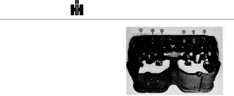
1. Exhaust Lever
4. Intake Lever
5. Install new bushing with ST-691 and arbor press.
2 Injector Lever
5. Injector Lever
3. Intake Lever
6. Exhaust Lever
a. On injector and exhaust valve levers, install
Fig. 3-4, (N10326). Rocker lever assembly
bushings so oil holes to crosshead nose or injector link
and adjusting screw are open for oil flow.
and secure shaft position with setscrew or oil spray
b. On intake valve levers, with oil drilling to
nozzle. Check all levers for freedom of movement on
crosshead nose end, install bushing so "nose" hole is
shaft to prevent galling.
closed and so "slot hole" is in line with adjusting screw oil
hole. Do not bore steel bushings.
Note: Oil spray nozzles are used on 80 deg. tilt engines.
6. Check intake and exhaust rocker lever-to-
Use ST-1182 Alignment Tool to obtain proper alignment
crosshead contact surfaces. If worn or damaged, grind
of oil spray holes in nozzle to permit oil flow from rocker
to original contour or replace with new rocker lever.
lever shaft to valve mechanism. Secure spray nozzle in
desired position with jam nut.
7. Check rocker lever shaft for wear or scoring. If
shaft has shoulders or ridges due to rocker lever action
5. Coat expansion (cup) plug contact surface with
on shaft, replace with new rocker lever shaft. See Table
sealant. Install new expansion plug in rocker lever
3-1 (2) for shaft dimensions. Flush out shaft bore and
housing using ST-1053 Driver.
dry thoroughly.
8. Current shafts are 12.880 inch [327.15 mm]
CRANKCASE BREATHER
long, older shafts are 13, 060 inch [331.72 mm]. Older
shafts can be reduced to new shaft length if oil leakage
Four different types of crankcase breathers are used on
has been encountered at the shaft cup seal plug.
855C.I.D. Series Engines. Mesh element with vapor
Machine equal amount from each end of shaft.
barrier, mesh element, paper element and screen
ASSEMBLY
element.
1. Install adjusting screws and locknuts in rocker
levers.
1. Remove cover, screens and baffle or element
from breather body; discard paper element.
2. Install cup type plug in rocker lever shaft with
ST-863 Cup Plug Driver. Coat rocker lever shaft with
2. Clean vent tube, screens and baffle or mesh
clean lubricating oil.
element in an approved cleaning solvent. Wipe out
3. Start shaft into housing, install levers on shaft as
breather housing.
shaft is pushed through housing. See Fig. 3-4 for
correct position of levers.
3. Assemble baffle, screens or element and new
gasket in body. Replace cover.
Note: Current engines using aluminum rocker lever
4. Index locking hole in shaft with locking hole in
cover with baffle plate, Part No. 210051, installed, do not
housing
have baffle or screens in crankcase breather body.
364