
TRUCK SERVICE MANUAL
ENGINE
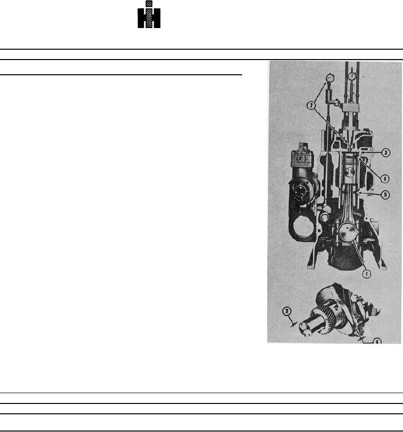
Table 14-1: Assembly Specifications - Inch [mm] (Reference Fig. 141)
Ref
Worn
New
New
No
Measurement
Limit
Minimum
Maximum
1
Main Bearing
Journal Clearance
0.007
0.0015
0.005
,
[0.18]
[0.038]
[0.13]
2
Connecting Rod Bearing
Journal Clearance 1
0.007
0.0015
0.0045
'U
[0.18]
[0.038]
[0.114]
3
Crankshaft
End Clearance
2
0.022
0.007
0.017
[0.56]
[0.18]
[0.43]
4
Cylinder Liner
Protrusion
3
0.003
0.006
[0.08]
[0.15]
,
Out of Round
0.003
Top One(1) Inch 4
[0.081]
Out of Round
0.002
Packing Ring (Lower) area
5
[0.05]
5
Connecting Rod
Side Clearance
6
0.0045
0.013
[0.114]
[0.33]
6
Gear Train (Gear to Gear) Crankshaft,
Camshaft, Accessory Drive and
Lubricating Oil Pump
Backlash
0.020
0.0045
0.0105
[0.511
[0.114]
[0.267]
7
Camshaft (With Thrust Plate)
End Clearance
0.001
0.005
[0.031
[0.13]
(With Outboard Bearing Support)
End Clearance
0.008
0.013
[0.20]
[0.33]
8
Injection Timing
7
Refer to Table 14-3
9
Injector, Crosshead and Valve Adjustments
Refer to Injector and Valve Adjustment
10
Dynamometer Testing
Refer to Test Procedure
11
Lubricating Oil Pressure
Refer to Table 14-15
12
Blow-By
Refer to Test Procedure
13
Back Pressure
Refer to In-Chassis Run-In
Crankshaft Flange Capscrew Torque Specifications - ft-lb. [kg m]
Engine Model
Part No
Minimum
Maximum
14
NT-Series
196653 Capscrew
250
270
196654 Retainer
[34.9]
[38.8]
392