TRUCK SERVICE MANUAL
Note: The throttle lever stop in the vehicle chassis
Note: Install enough shims to bring the plunger flush with
should be adjusted so there will be a minimum or
the fuel passage leaving it completely open for pump
negligible amount of collapsing of the throttle lever.
calibration, Fig. 5-103. Some throttle shafts do not have
Otherwise, the purpose of the spring loaded lever will be
a restriction plunger.
defeated as the lever can collapse only so far. When the
throttle linkage stop is not properly adjusted, the spring
2. Install restriction plunger in the throttle shaft, if
loaded lever may permit the bell crank in the linkage
used. Torque plug to 40 to 55 inch pounds [4.5 to 6.2 No
mechanism to go "over center," locking the throttle in full
m].
fuel position.
Governor Plunger
3. Install washer over shaft. Insert the throttle shaft
In sleeve so the "ears" of the stop are curved downward
1. Lubricate with engine oil and install the plunger
or if pin is used so open side of pin is down, lubricate
into barrel. Fig. 107. Make sure plunger is correct fit
with fuel oil.
and change
Note: Counterbored port on PT (type G) throttle must go
4. Install the snap ring and lock in the groove in front of
the throttle shaft cover plate.
Fig. 5-107 F566. Installing governor plunger
number if replaced. Remark governor barrel if oversize
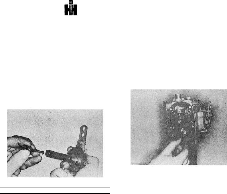
Fig. 5-103, F564. Installing throttle restriction plunger
plunger is used, so size of barrel and plunger
correspond.
Table 5-12: Throttle Shafts 1/2" PT (type G)
Drive Cover Assembly
Code
Red
1. Place a new gasket over the pump housing
Size
0
dowel pins.
Part No.
149030
2. Place the assist plunger In the weight shaft bore
with spring and shims, when required.
Throttle Lever
3. Hold the governor weights in to hold the assist
Install the throttle lever on throttle shaft and tighten
plunger while assembling cover to housing,
securely. Throttle levers are available in lengths of about
meshing with tachometer gear.
1-1/4 to 5 inches (31.7 to 127 mm]; use the correct
length for the pump application.
4. Position plunger drive tang horizontally position
weight carrier horizontally.
The spring loaded throttle lever is used to prevent throttle
shaft bushing wear and scoring that can occur when
Note: The weights straddle the governor plunger driver.
excessive pressure is applied to the throttle lever In full
5. Torque capscrews 9 to 11 foot pounds [12 to 15
fuel position. The spring loaded lever is designed to
No m], securing cover to housing.
collapse under this excessive pressure and then spring
6. Rotate drive shaft to be certain tachometer gear
back when the pressure is released.
meshes.
This will also prevent the throttle lever from turning on
the shaft and mutilating the serrated shaft diameter.
515

