
TRUCK SERVICE MANUAL
FUEL SYSTEM
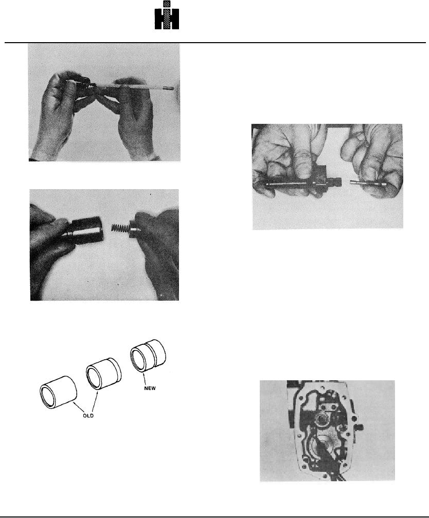
Throttle Shaft
Fuel Adjusting Screw Type
1. Lubricate "O" ring and slide on fuel adjusting screw.
2. Insert fuel adjusting screw into throttle shaft about 6
turns. Do not- restrict throttle shaft fuel port. Fig. 5-101.
3. Lubricate "O" ring and slide on throttle shaft.
Fig. 5-97, F558. Installing washer over idle screw
Fig. 5-101, F5307. Installing fuel adjusting screw in
throttle shaft
4. Insert throttle shaft in housing with counterbored port
down and throttle stop slanted down in standard
automotive pump.
5, Instali snap ring on end of throttle shaft. Fig. 5-102.
Restriction Plunger Type
Fig. 5-98, F559. Installing idle plunger button
Throttle shafts vary with applications. Replace with same
type throttle shaft, if needed. Table 5-12 and 5-13.
1. Install new "0" ring on throttle shaft using ST-835
Sleeve for 1/2 inch [12.7 mm] (ST-422 for larger) shaft to
avoid damage to "0" ring. Lubricate before assembly.
Fig. 5-99, F5149. Old and new design idle plunger
buttons
Fig. 5-102, F5299. Installing snap ring in throttle shaft
514