
TRUCK SERVICE MANUAL
FUEL SYSTEM
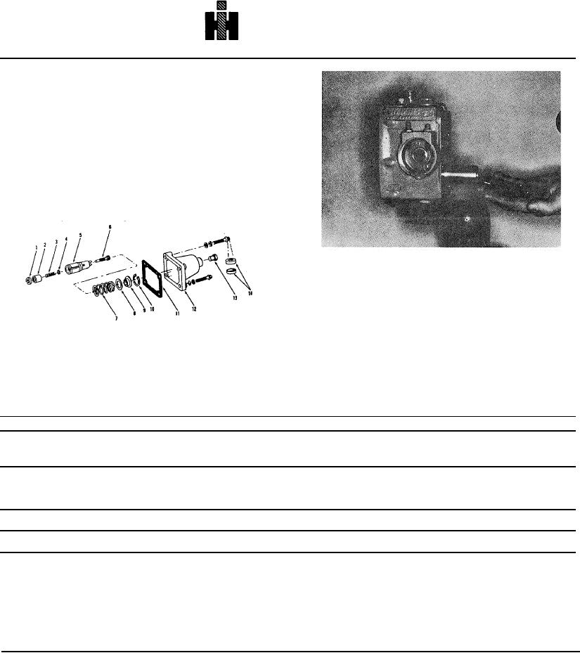
GOVERNOR SPRING PACK
The governor spring pack consists of the idle and
maximum or high-speed springs, plungers, adjusting
screw and shims. The springs control engine speed and
adjustments are made by the shims or adjusting screw.
Fig. 5-68
Standard Automotive Spring Pack
Disassembly
1. Remove snap ring which holds governor spring pack
in sleeve with a pair of snap ring pliers.
Fig. 5-70, F510. Removing standard spring pack
assembly
2. Remove high-speed spring, spring retainer and shims
from spring-pack housing.
3. Remove idle-spring plunger guide (adapter when
used), idle spring or springs, idle spring plunger and
spring rest washer. Fig. 5-70.
1
ADOPTER
6
ADJUSTING SCREW
11
GASKET
2
IDLE SPRING PLUNGER
7
HI-SPEED SPRING
12
COYER
See Fuel Pump Assembly section for assembly of
3
IDLE SPRING
8
SHIM
13
PLUG
governor
spring
pack
to
fuel
pump.
4
WASHER
9
RETAINER
14
SEAL
5
GUIDE AN CLIP
10
SNAP RING
Fig. 5-68, F5148. Standard governor - exploded view
Table 5-10: Governor Springs
Inches
Free
Part
Color
Wire Dia Number
Pounds
Length
Length
Number
Code
Replaces
Inch [mm] Coils
Load [kg]
@ [mm]
Inch[mm]
Maximum or High Speed Springs and Specifications
*143251
Blue/Purple
70711B
086[2.18]
8.4
11.65/10.75[5.28/4.89]
@ 1.06[25]
1.487[37.8]
*Formerly color coded - 143251 Red/Black and Blue/Brown
Weight Assist Springs and Specifications
143847
Blue
028[.711]
9.7
3.30/3.70[1.50/1.68]
@ .325[8.2]
584114.8]
Idle Springs and Specifications
144195
None
(Idle) Std. Auto
032[.813]
12
0.69/0.85[.31/.38]
@ .955[24]
1.025[26.0]
FUEL PUMP ASSEMBLY
Vise And Holding Fixture
The pump assembly requires all parts to be dirt free, and
the actual operations performed with the utmost care, to
Mount the fuel pump on Holding Fixture ST-546 or
insure proper and trouble-free performance.
3375133 and Swivel Vise ST-302.
512