
TRUCK SERVICE MANUAL
FUEL SYSTEM
Kit, Part No. AR-05592, enables valve to operate against
the higher fuel pressure plus the spring load.
Disassembly And Inspection Of Standard Cover
The orifice disc, with the center hole, restricts the fuel
1. Check governor weight carrier shaft in Its bushing
pressure loading on the spring loaded disc. This allows
before removal. Excessive wear can be felt by moving
the spring loaded disc to operate like the standard disc
shaft from side to side in the bushing.
without the fuel pressure effect.
2. Observe gear backlash between weight shaft gear
The high pressure valve will be valuable In applications
and
having shut-down controls where immediate starts are
required after a control has broken the electrical circuit.
The engine may be started with this kit as soon as the
operator desires.
Arrangement of AR-05592 kit in the shut-off valve is
shown in Fig. 5-44.
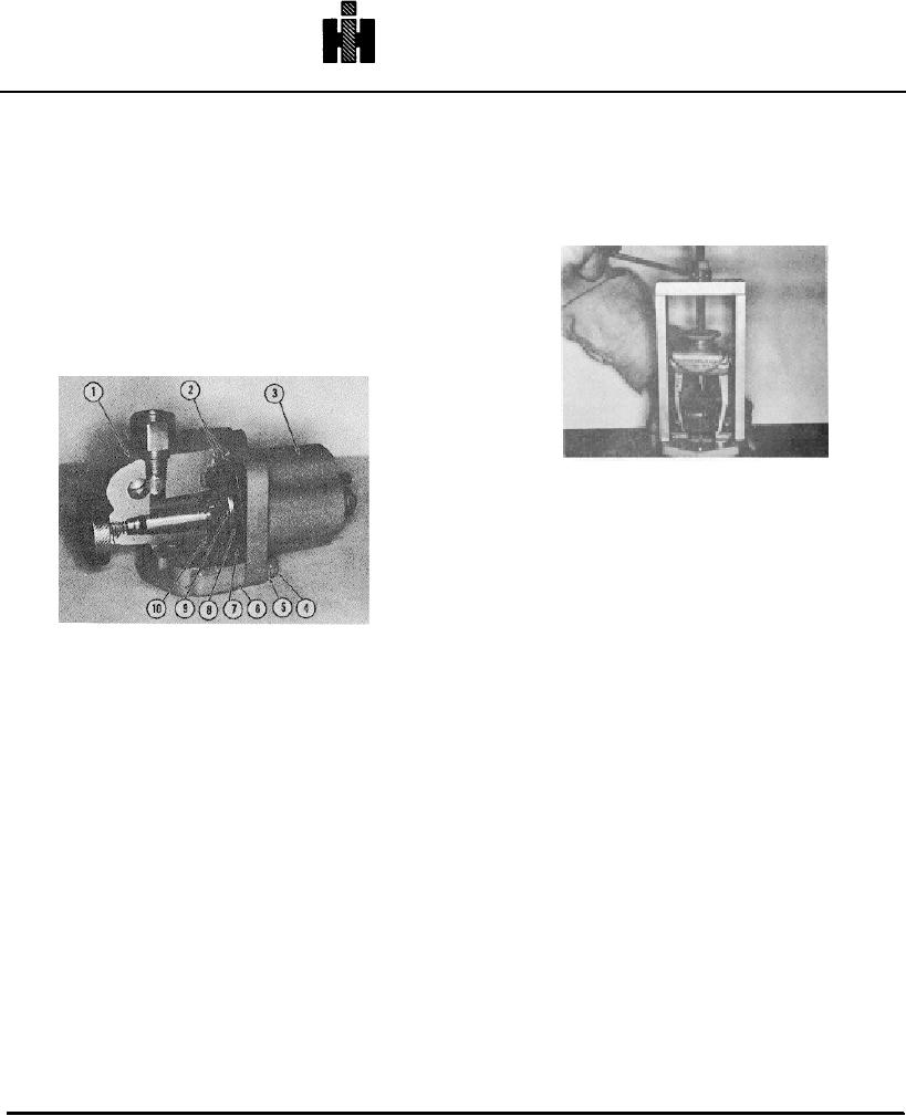
Fig. 5-47, F538. Using ST-709 to pull governor weight
assembly
drive gear. Normal backlash is 0.005 to 0.009 Inch [0.13
to 0.23 mm] .
Note: Remove weight assist plunger If not previously
removed.
3. To remove governor weight carrier assembly from
drive cover use ST-709 Puller to pull weight shaft
assembly and bushing from front cover. Fig. 5-47. The
1
HOUSING ASSEMBLY
5
S607 LOCKWASHER
8 129768 SPRING
2
19888 "O" RING
4
RED
9 196056 DISC, ORIFICE
bushing is locked on shaft with a snap ring and will
3
OIL ASSEMBLY
6
19605 5 SPACER
10 19605117 DISC PILOTING
usually come out of cover with weight shaft assembly,
4
S1215 CAPSCREWS
7
129839FUELSHIELD
(10-24X3/4)4 - REQD.
however, if snap ring pulls off shaft leaving bushing In
Fig. 5-44, F5232. High pressure fuel shut-down valve
front cover, use an internal engaging puller of ST-709 to
Assembly
pull bushing. If shaft pulls off of cast carrer, use ST-667
1. Remove solenoid from valve body. Discard standard
to remove shaft and bushing.
disc in valve body. Retain wave spring and stainless
4. Remove fuel pump drive coupling retainer capscrew
steel plate.
and washers. If cover contains tachonmeter drive, pull
2. Place spacer block on valve body with "O" ring groove
coupling with ST-709 puller or pull spline drive coupling
toward solenoid. Make sure "O" rings are in grooves In
with ST-1249.
valve body and spacer block.
5. If cover contains tachometer shaft, remove drive
3. Insert orifice disc, with hole In center, in valve body.
cover retaining screw and lift off drive cover.
Insert piloting disc, with no center hole, In spacer block.
6. Use ST-667 dowel puller or brass punch to remove
4. Place wave spring on raised portion of top disc fuel
tachometer shaft, seal and bushing from front cover;
shield. Place stainless steel plate on wave spring and
discard seal.
attach solenoid with 10-24 x 3/4 Inch [19 mm] screws
7. Remove large snap ring from. pump end of drive
supplied.
shaft between drive cover and drive gear with hose
Front Cover Assemblies
clamp pliers or grind a small groove in a pair of needle
Front cover assemblies consist of the cover, main shaft
nose pliers. Fig. 5-48.
and bearing, and the governor weight carrier assembly.
8. If cover does not contain tachometer drive, Install a
Most front covers built after Jan. 1975 will contain the
longer capscrew In place of drive coupling retainer
tachometer drive. The cover may be flange mounted to
capscrew, press on capscrew to remove drive shaft
the compressor or fuel pump drive, or the pump bracket
bearing and shaft assembly from front cover. Fig. 5-49.
mounted to the engine.
9.
Press drive shaft oil seals from drive cover.
508