
TRUCK SERVICE MANUAL
FUEL SYSTEM
gears on shaft 0.680 to 0.690 Inch [17.27 to 17.53 mm]
check for error in assembly which must be corrected to
from body end of shaft. Oil shaft before assembly.
prevent early pump failure.
5. Check lubrication holes in cover and body; they must
5. If cooling feature is used, install elbow and/or check
be clean.
valve. If 1/8 inch [3.17 mm] pipe plugs is used, torque to
10 to 13 foot pounds [14 to 18 No m].
6. Clean cooling kit components, if used, and dry with
compressed air.
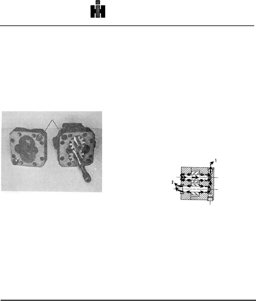
Integral Type PT (type G) Fuel Pump Cooling
The small amount of fuel which is routed back to fuel
Assembly 1. Lubricate and slide shafts and gears into
tank, previously was recirculated internally, Therefore,
cover. Make sure parts are clean.
this method of cooling does not use any of normal
delivery of gear pump and present fuel pump calibration
2. Position new gasket and install body to cover. Align
specifications will still apply.
locating notches together. Fig. 5-33.
This bleed fuel is that fuel which flows through and
lubricates gear pump bearing bores. Previously, this fuel
was dumped back into suction side of gear pump. With
integral bleed gear pump, the lubricating fuel flow through
three gear pump bearings is bled off through an external
tapped drain hole. The former internal pump drillings
which permitted this fuel to return to the suction side,
have been eliminated. Fig. 5-34.
Fig. 5-33, F524. Locating notches for right hand pump.
Note: Location of notches and drive shaft determines
pump rotation.
1. TO INJECTOR DRAIN LINE OR FUEL TANK
2.TO FUEL PUMP HOUSING
3. When a right hand rotation pump is being assembled,
Fig. 5-34, F5157. Gear pump fuel flow
place the driven gear shaft of the gear pump in the
pocket nearest the locating notches. Place the driving
The inboard main shaft bearing bore still returns its fuel
gear shaft in the other pocket. The ring dowel is always
to the gear pump suction. The inboard idler shaft bearing
located around drive shaft.
fuel flows through the hollow idler shaft to the external
4.
Secure cover and body with dowels, tighten
drain line. As can be seen from the sketch, both
capscrews to 11 to 13 foot pounds [15 to 18 N. m].
outboard gear pump bearings drain externally.
Check to see that pump turns freely with finger pressure.
Note: Total gear backlash must be 0.001 to 0.004 inch
Since three of the bearing bores drain externally, it is
[0.025 to 0.102 mm] The drive shaft must protrude 2.370
apparent that both tapped holes in the gear pump
to 2.412 inch [60.2 to 61.3 mm] from the body. End
housing cannot be plugged. Plugging both tapped
clearance should not exceed 0.0015 inch [0.0377 mm]
openings will prevent lubricating and cooling fuel flow
nor be less than 0.0009 inch [0.0228 mm]. Gaskets are
through the three bearing bores and gear pump seizure
available in .0020 inch [.051 mm] (red) and .0015 inch
will occur.
[.038 mm] (purple). If pump binds or has excessive play,
505