TRUCK SERVICE MANUAL
FUEL SYSTEM
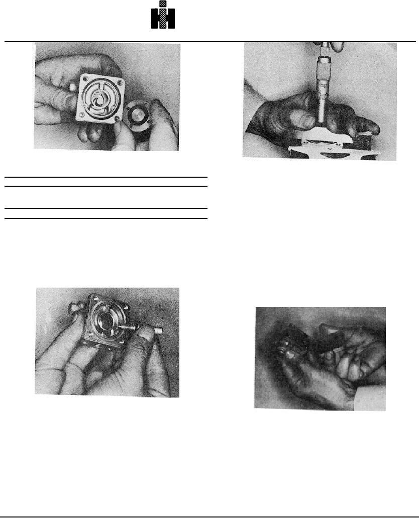
Fig. 5-38, F528. Inspecting plate type valve
Fig. 5-40, F530, Checking shaft tip depth
Table 5-6: Coil Resistances
Coil
4. Apply lubricant to housing "O" ring and seat in groove.
Coil
Voltage
5. Drop spring washer on valve with concave side up
Part No.
And Type
(Ohms)
and piloted around valve locator. Fig. 5-41.
7.5 0.5
134072
12 V.D.C. Single Terminal
6. Place fuel shield on valve housing and tighten screws
to 25 to 30 inch pound [2.8 to 3.4 N- ml torque.
Assembly
7. Energize valve and pump fluid through valve at 300
1. Install a new "O" ring on new override shaft and coat with
psi [2068 kPa]. De-energize valve and valve should
lubricant. Fig. 5-39.
withstand the 300 psi [2068 kPa] load with no leakage
2. Screw shaft into housing until it reaches bottom of its
through valve.
bore. Use depth micrometer set at 0.118 Inch [2.997 mm]
8. Should leakage exist, check the main body for nicks
and check distance from face of valve housing to tip
or depressions where body and plate come in contact.
Check the rubber seal in the plate for swelling or other
defects.
Fig. 5-39, F529. Installing override shaft
Fig. 5-41, F531. Assembling shut-down valve
of shaft. If necessary, screw shaft out until it is 0.118 inch
[2.997 mm] below housing face. Do not move shaft and
High Pressure Fuel Shut-Down Valve
press on knob until it contacts valve housing which will act
Some applications and/or approval tests require that
as a stop. Fig. 5-40.
rapid successive engine starts be made. Starts are
3. Place valve into valve housing with rubber side toward,
attempted as soon as the flywheel stops. Rapid starting
housing.
in this manner places an overload on the solenoid valve,
since it must open against pressure that has not
dissipated from the previous operating cycle. Fire engine
applications are an example of this requirement.
507

