
TRUCK SERVICE MANUAL
FUEL SYSTEM
1. Remove felt seal, when used, and oil seal from
tachometer drive shaft.
2. Press tachometer drive shaft from drive gear and
bushing, if the gear is badly worn or shaft and bushing
are galling or scoring. Check shaft outside diameter and
bushing inside diameter. Replace if necessary. Table 5-
4.
Assembly
Place bushing on tachometer shaft with chamfered end
of bushing toward gear end. Press gear onto shaft until
Fig. 5-27, F5304. Removing AFC barrel retaining ring.
flush
8. Slide plunger and piston/bellows assembly from tool
and into barrel. Insert very carefully to avoid damage to
the "Glyd" ring. Fig. 5-25.
Caution: Make sure plunger and "Glyd" ring
assembly have been in forming tool for a minimum
of thirty minutes to establish a contoured form.
9. Cup bellows downward between piston and housing
to insure bellows does not wrinkle when cover is
installed.
10. Line up bellows holes with housing and cover plate
holes, install capscrews and washers. Capscrews are to
be tightened to 30 to 35 in-lbs [3.4 to 4.0 Nm] torque
after setting AFC on test stand. Fig. 5-24.
11. Install lubricated "O" ring on needle valve using
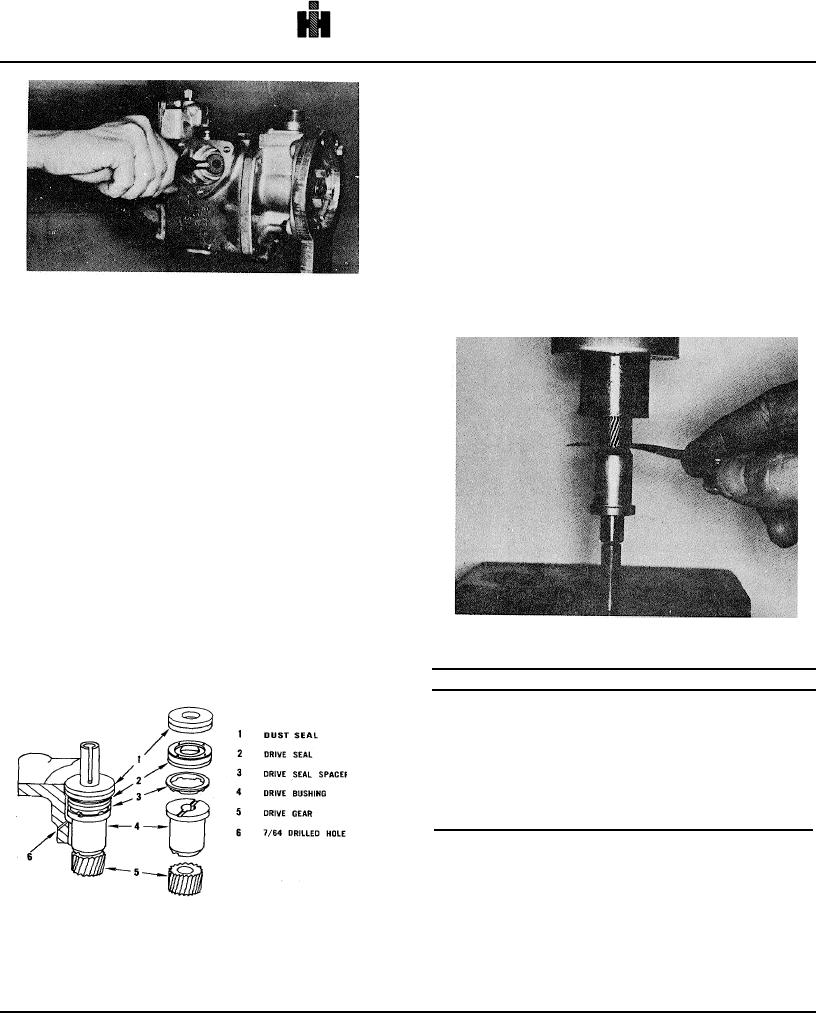
Fig. 5-29, F537. Pressing tachometer gear on shaft
assembly tool No. 3375148 and screw into housing
above throttle shaft until it bottoms in housing; install jam
nut loosely until set on test stand.
Table 5-4: Tachometer Drive Parts Specifications
Part Description
In. [mm]
Front Cover
Mounted
Tachometer Shaft
.3950/.3955 [10.033/10.046]
Shaft Bushing
.3963/.3970 [10.066/10.084]
Housing Mounted
Tachometer Shaft
.3100/.3105 [7.874/7.887]
Shaft Bushing
.3120/.3130 [7.925/7.950]
with end of shaft. Fig. 5-29. Check to see that shaft
turns freely in bushing. Maximum clearance between
gear and bushing is 0.005 Inch [0.127 mm].
Fig. 5-28, F5214. Tachometer drive parts in housing
Note: Check gear to make sure it matches with
tachometer drive gear. Fig. 5-30.
Tachometer Drive - Mechanical
Disassembly
503