
TRUCK SERVICE MANUAL
FUEL SYSTEM
Both ends of through drain drillings are tapped so that
SHUT-DOWN VALVES
gear pumps can be converted from R.H. to L.H. In
normal manner.
The shut-down valve, electric or manually operated,
Caution: Under no circumstances should the pump
controls flow of fuel from the pump to the injectors. The
be operated with cooling return flow plugged. This
electric valve is equipped with a knob which will open the
valve. In case of electrical power failure, keep in
fuel flow is necessary to lubricate the bearing
counterclockwise position to operate electrically.
surfaces within the gear pump.
1. Fuel pumps with the integral cooling feature may be
Electric Shut-Down Valve
identified by a 1/8 inch N.P.T.F. hole In top of gear
The electric shut-down valve is held open while current is
pump.
flowing through the electric coil, or solenoid. When
2. Install elbow-check valve, Part No. 175836, in 1/8
current is not flowing, valve will shut unless the shut-
inch drain hole in gear pump. A 1/8 inch N.P.T.F. brass
down valve is locked open manually.
street elbow and a check valve, Part No. 179037, may
Disassembly
be used as a substitute for valve combination.
Remove coil housing from valve housing. Remove coil
Note: The spring-loaded check valve is necessary to
housing, fuel shield and discard "O" ring. Remove spring
prevent fuel in pump from draining away and causing
washer and plate-type valve. Remove manual override
hard starting.
knob, and unscrew override shaft from coil end. Discard
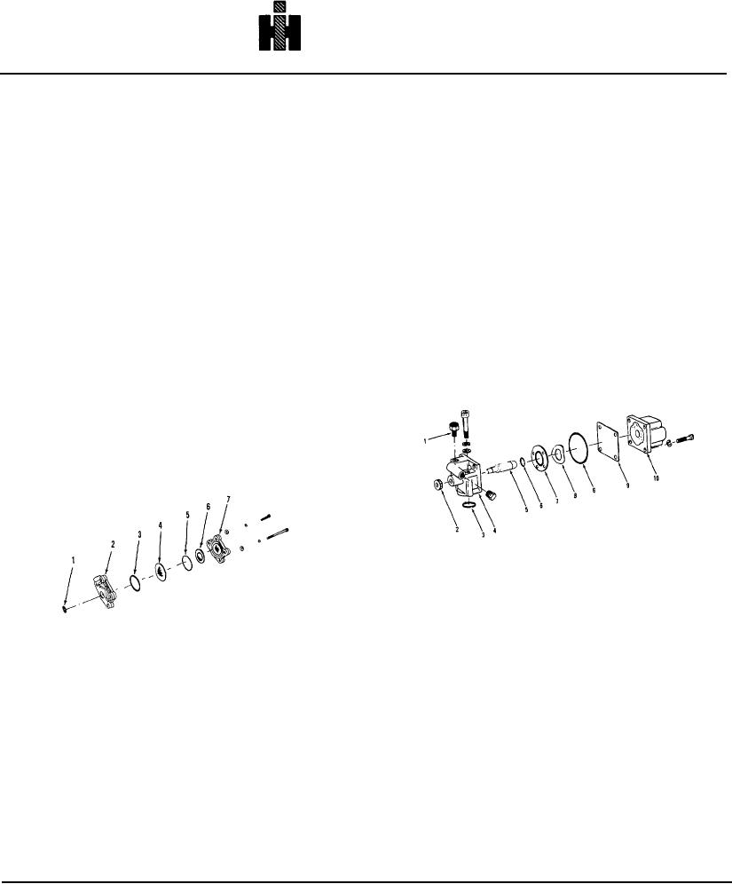
Pulsation Damper
shaft and "O" ring. See Fig. 5-37.
Disassembly And Inspection
1. Remove housing from cover. Remove spring steel
diaphragm. Discard "O" rings and nylon washer.
Note: Diaphragm must be kept clean prior to assembly.
1 CONNECTION
6
'0' RING
2 KNOB
7
VALVE
3 SEALING RING
8
SPRING
4 HOUSING
9
SHIELD
5 SHAFT
10
COIL
1 SEAL
5
'0' RING
2 BODY
6
NYLON WASHER
Fig. 5-37, F5143. Electric shut-down valve - exploded
3 'O' RING
7
PLATE
view
4 DIAPHRAGM
Cleaning And Inspection
Fig. 5-36, F5132. Pulsation damper - exploded view
1. Clean all parts except the coil assembly in mineral
spirits.
2. Check for corrosion, excessive wear or cracks In
Note: Do not wet the coil with solvent; instead, wipe it
cover or diaphragm. Replace if necessary. Fig. 5-36.
clean with a lint free cloth.
2. Visually check valve and valve seat for wear, bonding
Assembly
failure or corrosion. Replace if necessary. Valve seat
1. Install new "0" rings In grooves and new nylon
should have a minimum seat 0.015 inch [0.38 mm] wide.
washer.
Fig. 5-38.
2. Coat the diaphragm with a good grade of 10W or
3. Check coil assembly with an Ohm meter, replace if
20W oil and lay in cover.
below values given in Table 5-6.
3. Assemble cover to housing, torque capscrews to 11 to
Caution: Be sure starting switch is in off position
13 foot pounds [15 to 18 No m].
when checking coil.
506