
TRUCK SERVICE MANUAL
FUEL SYSTEM
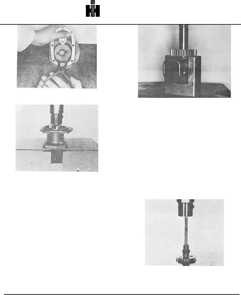
Fig. 5-48, F539. Removing snap ring from groove
Fig. 5-50, F5285. Removing gear from weight carrier
with ST-1231
3: Slip governor carrier bushing on the carrier shaft with
flanged end of bushing next to gear and secure bushing
withsnap ring.
Drive Shaft
Disassembly
1. Press gear pump drive coupling or tachometer drive
gear, when used, and governor drive gear from drive
shaft. Fig. 5-52.
2. Remove front cover tachometer drive gear with small
gear puller, remove key.
Fig. 5-49, F5144. Press drive gear assembly from front
cover
Note: Press away from bearing because shaft has a
shoulder under bearing.
10. Governor assembly can be disassembled to change
gear and bushing. The governor qarrier, weights and
shaft can only be replaced as an assembly. If bushing is
worn larcer than 0.504 onlych [1280 mm],be replace
bushing.
Governor Weight Carrier
Welded and cast governor weight carrier assemblies
must be purchased as a complete unit. These pins
cannot be replaced.
1. If cast carrier shaft has pulled off in removal from
cover, press shaft into carrier until end of shaft is flush to
0.005 inch [0.13 mm] below carrier surface (weight side).
Note: Do .not reuse parts unless there is a minimum of
0.0005 Inch [0.013 mm] interference fit between shaft
and carrier.
2. If removed, press on gear Do not press against carrier
Fig. 5-52, F5146. Press shaft from gears
as it may be damaged. Press against inside end of the
carrier
shaft, If possible. The rough edge of gear goes toward
carrier weight.
509