
TRUCK SERVICE MANUAL
FUEL SYSTEM
Tachometer Drive In Housing The life of tachometer
drive seal can be significantly improved by keeping
maximum clearance between gear and bushing to .005
inch [0.127 mm] and by correctly installing drive
assembly into fuel pump housing.
1. Line up oil groove in top of bushing with fuel pump
drive shaft. Press bushing, shaft and gear assembly into
housing with ST-1032 Driver until bushing bottoms.
Note: Using any tool but ST-1032 Driver may cause
indentations In oil seal which leads to premature seal
failure.
2. Install spacer on top of bushing with slotted edge
down. Install new oil seal, with spring side down, with
ST-1032 Driver. Spacer must bottom on bushing.
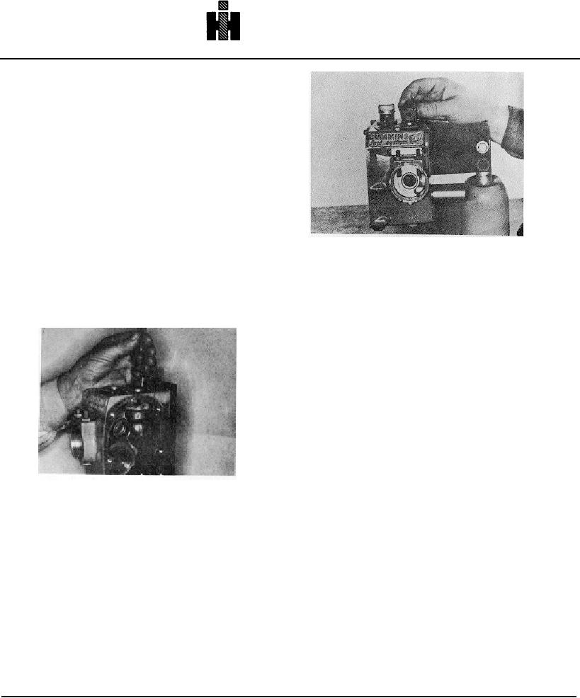
Fig. 5-95, F557. Installing fuel screen in standard
Caution: Do not overpress spacer.
It can be
housing
flattened eliminating its effectiveness.
Double Screen
3. Cover top of seal with a thin coat of lubricating oil.
1. Install lower screen (one with holes in each end),
Install new felt dust seal with white side up. Secure
install screen retainer and new "0" ring.
tachometer cover with new gasket to housing.
2. Install upper screen, hole down; install spring.
3. Lubricate new "O" ring and plate on cap, torque cap 8
to 12 foot pounds [11 to 16 N. ml.
Governor Spring Pack
Automotive Governor
PT (type G) Fuel Pump
1. Assemble idle screw into plunger guide, place small
washer over screw point inside guide. Fig. 5-97. Place
small idle spring into guide and place idle plunger
(button) against spring in guide. Fig. 5-98.
Note: When assembling governor spring pack, the new
improved plunger should be used. Fig. 5-99.
2. The size of counterbore changes with different engine
Fig. 5-94, F556. Installing tachometer drive
models. See pump calibration data for correct plunger to
use. The plunger controls maximum fuel pressure
Filter Screen
produced by the fuel pump.
Single Screen Types
Spring Pack Notes
1. Assemble the filter screen assembly into top of
Note: There are different maximum-speed springs
standard housing, hole in retainer goes down. Fig. 5-95.
available and each is identified by color stripes. See
Governor Spring Pack section, Table 5-10, for tabulation
2. Install "O" ring using grease to hold in place.
and specifications.
Note: Shims are available In 0.005, 0.010 and 0.020 inch
3. Position spring and tighten cover in place. Torque
[0.13, 0.25 and 0.51 mm] thickness. The final number of
cap to 8 to 12 foot pounds [11 to 16 No m].
shims must be determined during fuel pump calibration.
Overtightening is not necessary or desirable.
Install the spring pack cover and new gasket. Secure
cover to housing, torque capscrews to 9 to 11 foot
pounds [12 to 15 Nm]
513