
TRUCK SERVICE MANUAL
Fig. 5 1-8, F5103. 50 cycle motor brush location to
reverse motor
6. The last six spaces on the second line give the
calibration card number and suffix letter. 0101-11521-
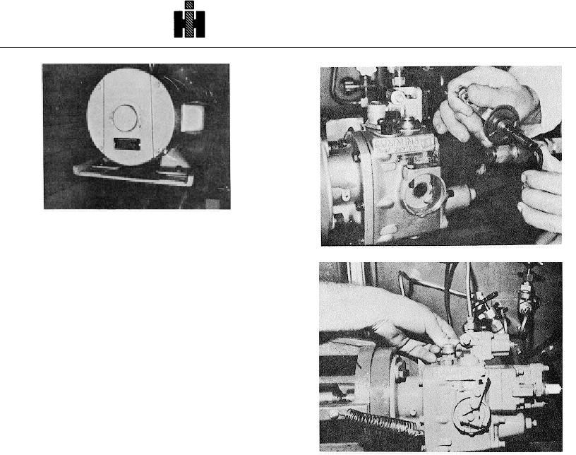
Fig. 5-1-11, F5104. Shim throttle restriction plunger
846067 L-BM-704862433C.
7. On fuel pumps with torque modification device, a
second nameplate will show regulator code number and
setting in thousandths of an inch.
Note: On Woodward governor pumps, the BM or AR
number will be for fuel pump only.
Run-ln
1. Remove throttle lever cover snap ring and pull shaft
from housing. Inspect restriction plunger to b(e certain
hole is shimmed completely open. Fig. 5-1-11. This is
not necessary if calibration is being checked as a trouble
shooting step. Replace shaft.
2. Move and hold throttle control lever to full fuel
Fig. 5-1-12, F5171. Opening shut-down valve
position, it may be necessary to adjust the throttle screws
to Insure that the fuel port in the throttle is fully open and
Calibration Procedure Flow Meter Method
indexed with the fuel passage in the fuel passage in the
Set Governor Cut-Off Speed
body. It is not necessary to adjust the throttle screw If
Standard Automotive Governor
the calibration is merely being checked as a trouble-
1. Close idle, leakage and pressure valves. Open flow
shooting step.
control or needle valve wide open.
3. Open completely the fuel pump shut-down valve, by
2. Increase pump speed to engine rated speed.
turning knob clockwise (manual button, Fig. 5-1-12) and
flow control valve. Open throttle, wide open positron,
3. Adjust vacuum valve in fuel pump suction line to
(secure open with a spring) start and run pump at 500
obtain 8 inch [203 mm] Hg. on vacuum gauge. Fig. 5-1-
rpm
14.
4. If pump is newly rebuilt or has been opened, run at
4. If you cannot obtain 8 inch [20.8 check of vacuum,
slightly over rated speed for five minutes to flush, allow
check for restriction min test stand filter or fuel supply
bearings to seat and to purge all air from the system.
line.
5. Before starting calibration, check pump fuel flow in
5. Close the fuel manifold orifice valve or main flow
the flow-meter for air. If air is present, correct leak
control needle valve until the flow-meter shows the flow
before continuing test.
specified under "Flow-Meter" in the calibration data (425
6. The test oil or fuel temperature must be 90 deg. to
Ib/hr on an NH-22Q pump). There must be no air visible
100 deg. F [32 deg. to 38 deg. C].
in the flow-meter. Fig. 5-1-15. Disregard change in
vacuum readings at this setting.
7. Set gear pump at 8 inch [203 mm] Hg.
vacuum
during run-in.
525