
TRUCK SERVICE MANUAL
throttle stop screw in or out until cc delivery comes to
Set Idle Speed Standard Automotive Governor
specifications. This setting is extremely important as it
affects the deceleration time of the engine. All pumps
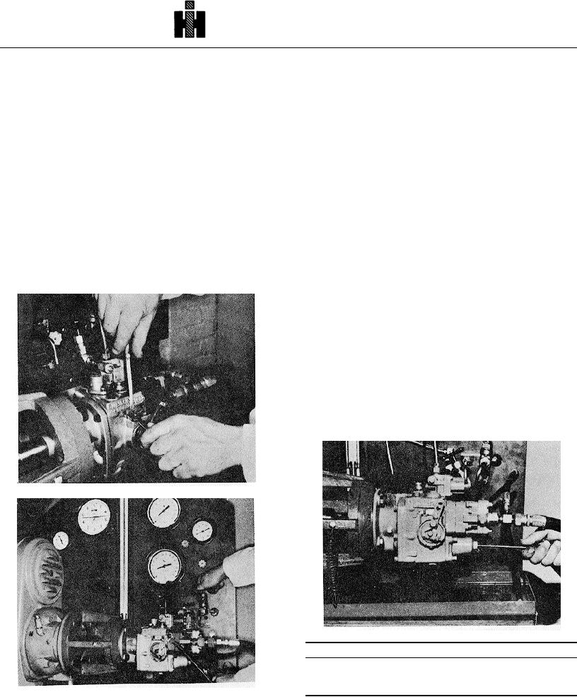
1. Close main flow control valve and open idle orifice
must be capable of attaining 15 cc minimum leakage.
valve. Fig. 5-1-21.
Fig. 5-1-20.
2. Set throttle shaft in idle position (toward gear pump)
7. Check leakage with light and heavy lever load, If
and hold firmly against stop.
leakage is increased by additional pressure in the throttle
closed position, set leakage under these conditions.
3. Run test stand at speed indicated by "Idle Speed" In
the calibration data.
8. If test oil temperature exceeds 100 deg. F [38 deg.
C], stop test stand and allow test oil to cool. If
4. Check pressure on fuel manifold pressure gauge, it
temperature exceeds 135 deg. F [57 deg. C], drain and
should be indicated by "Idle Speed." If pressure is low,
replace with new test oil.
screw idle adjusting screw in with ST-984, this screw is
located inside governor spring pack housing. To lower
9. Lock screw when setting is correct and recheck.
pressure back out screw, Fig. 5-1-22. For example:
22 psi at 500 rpm.
10. Close throttle leakage valve, open main flow control
valve.
Note: In rare cases, where high assist settings are used
(if screw bottoms in guide and pressure is still low), It
may be necessary to add washer on the spring end of
the idle screw.
G-1. Adjust Fuel Manifold Pressure With Internal
Throttle Shaft Plunger
1. Place throttle in full fuel position. Close the idle orifice
valve and open the main-flow valve.
2. Run test stand speed up to rated speed of pump as
indicated by "Manifold psi @ rpm" in the calibration data.
Fig. 5-1-20, F5112. Adjust throttle leakage rate
Fig. 5-1-22, F5175. Adjusting automotive governor idle
Table 5-1-3: Idle Spring Plunger Data (Button)
Code
Part
Counterbore
No.
No.
Diameter Inch [mm]
50
140925
.2985/.3015 [7.58/7.66]
Fig. 5-1-21, F5113. Open idle orifice valve
3. Adjust fuel flow-meter to specified flow in calibration
data. Check fuel pressure on fuel manifold pressure
gauge.
528