TRUCK SERVICE MANUAL
8. Leakage may occur at the gear pump to pump
specifications at second check point, (i.e.; 7581 PSI @ 1500
housing gasket if gear pump is not positioned correctly.
RPM can be 7481 at recheck).
9. Tighten all car)screws, hose connections, pipe plugs
c. If pump checks within the published tolerance at first
and filter screen cap.
check point, it must check within the published tolerance at
second check point.
Housing Porosity Check
6. Manifold Pressure At Weight Assist Check Point
1. Fill fuel pump with clean fuel or te st oil.
Recheck of the manifold pressure at the weight assist check
point can vary + 1 PSI from the published specification. (i.e.
2. Remove suction fitting at gear pump and install
35-41 PSI manifold pressure can be 34-42 PSI at reflow)
fittings so an air pressure hose may be attached.
Check Pump Seals
3. Air supply hose line must be equipped with a valve
and gauge to control air pressure at a maximum of 20 psi.
1. With test stand operating at 500 rpm, close vacuum
4. Apply 20 psi air pressure; do not exceed 20 psi or
value in fuel pump suction line till vacuum gauge reads 15
damage to seals may result.
inches vacuum. The fuel flow control or needle value should
be open during this check.
5. Pour fuel or test oil over pump and examine carefully
for air bubbles, indicating leaks. Alternately wipe pump or
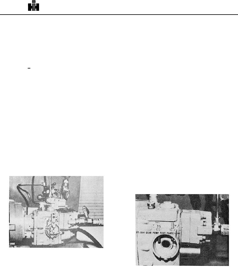
2. Put a small amount of Lubriplate or light cup grease
specific area dry and check for wet seepage. Do not use this
over the vent or "weep" hole at main shaft seal bore of fuel
check for seals.
Pump cover. Fig. 5132.
Gear Pump Test
3. If the lubricant is sucked into the hole at the 15 inch
vacuum setting, it is an indication that the seal will not permit
proper engine performance and should be replaced.
1. Use a "dummy" fuel pump built up with only the parts
required to drive the gear pump, minimum of pump body, with
4. The above check may also be performed on the
tachometer drive and a complete front cover assembly. If
throttle shaft to check the shaft "O" ring. Apply lubricant at the
desired, a complete fuel pump can be used if the governor
throttle bushing to shaft outside diameter.
plunger and weight assist plunger and spring assembly are
removed and pump housing is filled with fuel; this will prevent
5. Fill the tachometer seal bore with test oil from test
any possible damage to governor plunger or governor barrel.
stand, If the fluid is drawn Into the pump, replace the seal.
Gear pump may be mounted directly to test stand with adapter
bracket.
2. Install ST844 gear pump block plate, with gasket on
each side, between' gear pump and fuel pump body. Fig.
5-1-33.
Fig. 5132, F5172, Checking "weep" hole for leakage
7. During above checks, observe flowmreter for air in
the meter which may or may not indicate air leakage into
Fig, 5133, F5166. ST844 gear pump block plate
pump. Air may be entering lines between tank and pump. A
slow leak may not show up promptly as air in the meter.
3. Remove gear pump damper from gear pump and
Observe fuel level in tank for possibility of low fuel causing air
connect copper line from orifice block to gear pump pressure
bubbles.
tap.
533

