TRUCK SERVICE MANUAL
Adjust Fuel Manifold Pressure
Check Pressurizing Valve
Adjust fuel manifold pressure as indicated In standard
Loosen the variable speed throttle adjusting screw jam nut (top
automotive pump calibration.
screw) and locknut. Fuel should leak around the screw if the
pressure valve is properly pressurizing the housing. This can
also be done by loosening the plug in the standard governor
Compare Check Point Pressures
spring pack housing cover. Fig. 5127B.
Compare as indicated in standard
automotive
pump
calibration.
Weight Assist Pressure Check
Check as Indicated In standard
automotive
pump
calibration.
Recheck Specifications
1. When a PT (type G) fuel pump is calibrated on one
test stand and rechecked on another test stand, the calibration
values may vary. This can occur because test stands are not
exactly alike, due to manufacturing tolerances, gauge
tolerances, test oil viscosity variations, etc.
2. This variance can also occur with a pump is adjusted
on the engine and then checked on a test stand.
3. The current Calibration Unit program is aimed at
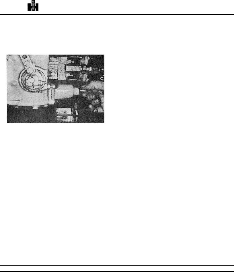
Fig. 5127B, F5272. Spring pack cover plug removed, pump
reducing test stand variations to an acceptable limit of +2 PSI
at 600 RPM.
from a given base line by correcting gauging and plumbing
Set Governor Cut Off
errors and checking procedures.
1. Set lower governor cutoff as indicated in standard
4. A tolerance has been established on fuel pump
automotive pump calibration to value listed in fuel pump
calibration values for rechecking pump' (A) On another fuel
calibration.
pump test stand or; (B) On any fuel pump test stand after it
has been calibrated on a test stand and then readjusted on
2. With pump operating at rated RPM, turn VS
engine. These tolerances are listed on the following pages.
maximum speed screw (top screw) in until pressure starts to
drop. Tighten the locknut.
5. If fuel pump is not within the tolerances listed under
"B" above, one or more of the following is indicated.
3. Check by increasing RPM until pressure starts to
drop. Set per VS governor cutoff in calibration.
a. Injectors are not properly calibrated and/or installed
and/or adjusted.
Set Throttle Leakage
b. Intake, exhaust or fuel suction restrictions are
excessive.
Set throttle leakage as shown in standard automotive pump
c. Engine has incorrect components for the particular
calibration. Adjust top screw of lower throttle shaft to set
fuel pump calibration involved. (Injector cups, camshaft,
leakage.
pistons, etc.) d. Pump was adjusted on engine to give other
than specified fuel manifold pressure and fuel rate.
Set Idle Speed
e. Test stand used for the recheck is not within
1. Set idle speed as shown in standard automotive
acceptable limits.
pump calibration with VS lever in full fuel position.
2. Return standard automotive throttle lever to full fuel
position. Move VS throttle lever to idle position and hold.
3. Adjust rear VS throttle adjusting screw to set idle at
same speed as the standard automotive governor or as
specified. Tighten locknut on jam nut.
Table 5-1-7: Idle Springs and Specifications
144195
None
(Idle) Std Auto
032[.813]
12
0.69/0.85[.31/.38]
@
955[24]
1.025[26.0]
531

