
TRUCK SERVICE MANUAL
Adjust suction valve to 5" Hg. or as close as possible.
3. Increase pump speed to rated rpm, normally 2100,
4. To adjust pressure to specifications, stop test stand
adjust test stand flow if necessary and check manifold
and remove the throttle shaft.
pressure.
5. Remove shims from the restriction plunger inside the
4. Shimming in TMD may be changed, in increments of
throttle shaft and replace assembly in fuel pump. Reset
.005 inch [0.13 mm], to adjust manifold pressure at rated
suction restriction valve to 5 inch [12.7 cm] Hg. after
speed.
setting internal throttle restriction. Repeat pressure
Special Throttle Travel
check and continue to remove or add shims until
On engines with hydraulic governors or other throttle
pressure indicated is 3 to 6 psi above "Manifold psi @
lever travel requirements the fuel pump throttle shaft
rpm value stated.
calibration Steps G-1 and G-2 are reversed as follows:
a. After each adjustment, reset flow as specified in
1. Using a protractor or ST-1162, set the fuel pump lever
calibration data, while maintaining vacuum at 5 inch 12.7
idle position centerline at 55 deg. from vertical on
cm Hg.
centerline of fuel pump throttle shaft. Lock throttle lever
b. If throttle shaft does not contain the restriction
screw. Set the centerline of the fuel pump lever in the
plunger, turn pump rear throttle screw until fuel manifold
maximum position at 27 deg. from vertical. (Step G-2
pressure and pump rpm is indicated by "Manifold psi @
on automotive fuel pump.) Lock rear adjusting screw.
rpm" in the calibration data. Lock throttle rear screw in
Recheck .throttle lever centerline travel; it must be 28
place.
deg., or as specified, between idle and full throttle. Fig.
G-2. Adjust Final Fuel Manifold Pressure With Rear
5-1-24 and 5-1-25.
Throttle Screw
Note: Do not adjust front throttle stop screw to set
1. After Step G1, where throttle shaft contains the
throttle lever travel.
internal restriction plunger, with pump running at speed
indicated by "Fuel Manifold Pressure", turn in rear throttle
screw until fuel pressure is reduced to value indicated.
Fig. 5-123. Lock screw in place.
2. Steps G-1 and G-2 are both necessary to properly
position the rear throttle screw where the throttle shaft
contains the internal restriction plunger.
3. Recheck governed speed and pressures
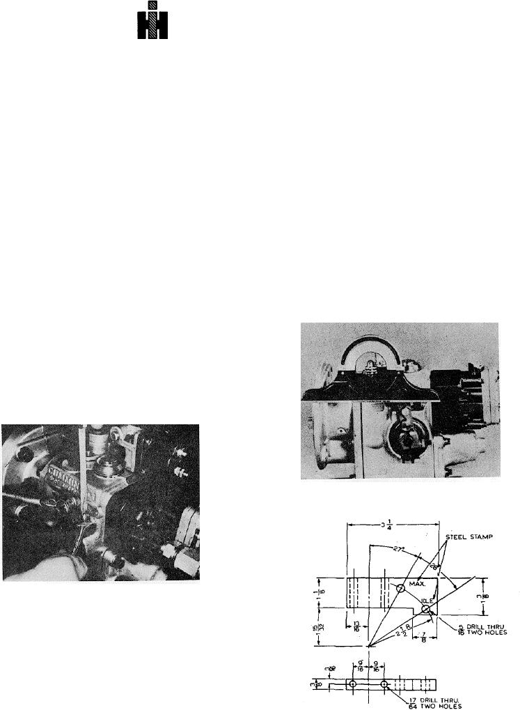
Fig, 5-1-24, F5239, Setting throttle travel with protractor
Fig.
5-1-23, F5115, Final fuel manifold pressure
adjustment
Adjustments With Torque Modifying Device
1. The throttle restriction plunger is set at 3 to 6 psi [21
to 41 kPa] above the specified rail at torque peak rpm.
(Normally 1300 rpm on PT-270 engines, pump code No.
2953.)
2. Set remaining throttle restriction at same rpm with
rear throttle adjusting set screw.
Fig. 5-1-25, ST-1162. Throttle travel template
529