
TRUCK SERVICE MANUAL
FUEL SYSTEM
Rebuild Instructions
Exterior of turbocharger should be cleaned before
disassembly. Mark compressor casing, diffuser plate, turbine
casing, bearing housing and clamps to facilitate assembly in
same position.
Disassembly
1. Remove fittings from lubricating oil inlet and outlet
ports.
2. Remove self-locking nut from compressor end of
rotor shaft. Fig. 10-6.
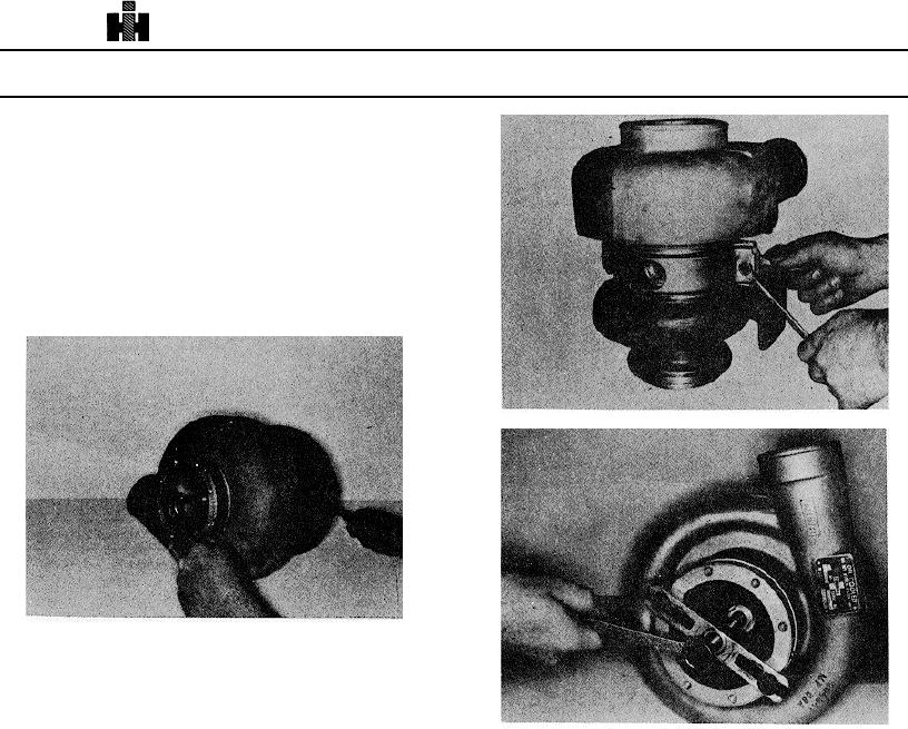
Fig. 10-7, T-416. Removing "V" clamps
Fig. 10-6, T-428. Removing self-locking nut from compressor
end of rotor shaft
3. Remove self-locking nuts, flatwashers and bolts
securing V clamp to turbocharger. Fig. 10-7. Lift off V
clamps; discard self-locking nut, flatwashers and bolts.
Fig. 10-8, T-516. Pulling impeller from rotor shaft
4. Using ST-647 Puller, secure clamp to collector
housing with end of puller bolt on rotor shaft. Pull collector
housing, oil seal diffuser plate and compressor wheel from
8. Position ST-881 Bearing Support over bearing
bearing housing Fig. 10-8.
housing and against turbine casing. Fig. 10-11. Place
assembly on press. Fig. 10-12. Press rotor assembly and
5. Remove capscrews, lockwashers, securing collector
bearing housing from turbine casing.
housing to oil seal/diffuser plate.
9. Invert bearing housing and gently tap rotor shaft on
6. Tap gently to loosen and remove diffuser plate from
workbench, Fig. 10-13, to remove rotor assembly from
the collector housing. Fig. 10-9. Remove and discard sealing
bearing housing. Lift out rotor assembly.
ring. Lift out compressor wheel.
10. Remove heat shield and insulation pad from bearing
7. Remove teflon bearing insert and floating bearing
housing.
from rotor shaft. Fig. 10-10. Remove "O" ring from bearing
housing; discard "O" ring and Teflon bearing insert.
11. Remove
sealing
sleeve
assembly
from
oil
seal/diffuser
560