
TRUCK SERVICE MANUAL
FUEL SYSTEM
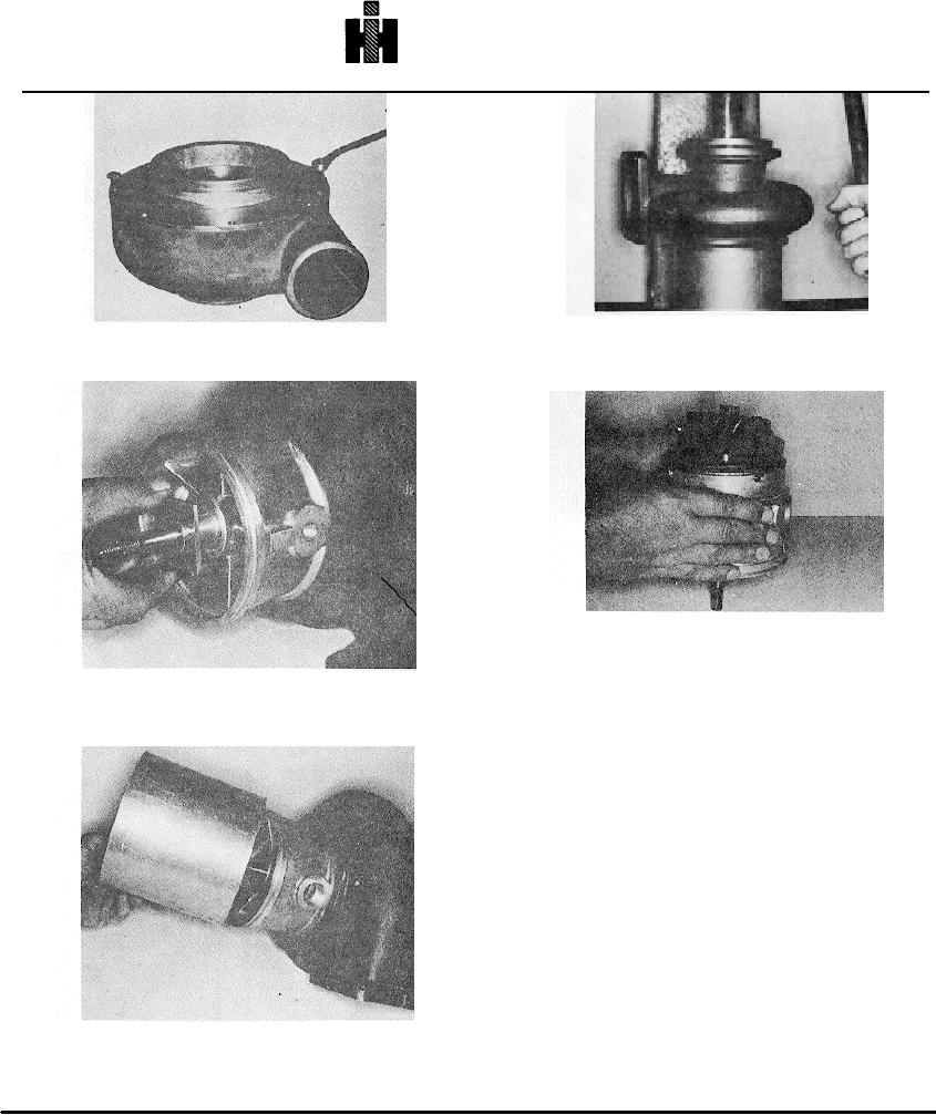
Fig. 10-12, T-519. Pressing rotor assembly and bearing
Fig. 10.9, T-418. Removing oil seal diffuser plate
housing from turbine casing
Fig. 10-13, T-430. Removing rotor shaft from bearing
housing
plate. Dsicard seal assembly.
Fig. 10-10, T429. Removing teflon bearing insert and
floating bearing form rotor shaft.
12. Remove sealing rings from grooves in rotor shaft.
Discard sealing rings.
Cleaning
Turbocharger parts accumulate hard, glazed carbon
deposits that are difficult to remove with ordinary
solvents. The cleaner used must be capable of removing
these stubborn deposits without attacking the metal.
1. Place all parts in a divided wire basket so parts will
not be damaged through contact. Do not pile in basket.
Be careful to avoid damage to all precision-ground
surface.
2. Immerse parts in Turko Super-Carb or similar solvent.
Caution: Never use a caustic solution or any type
solvent that may attack Aluminum, Stellite or Ni-
Resist alloys.
Fig. 10-11, T-518. positioning St-881 bearing support
over bearing housing and against turbine casing
561