
TRUCK SERVICE MANUAL
FUEL SYSTEM
Assembly
Caution: All parts and work area must be free of
grease, oil and dirt to keep abrasives out of
turbocharger during assembly and to obtain correct
dimensional stack-up of parts and prevent premature
turbocharger failure.
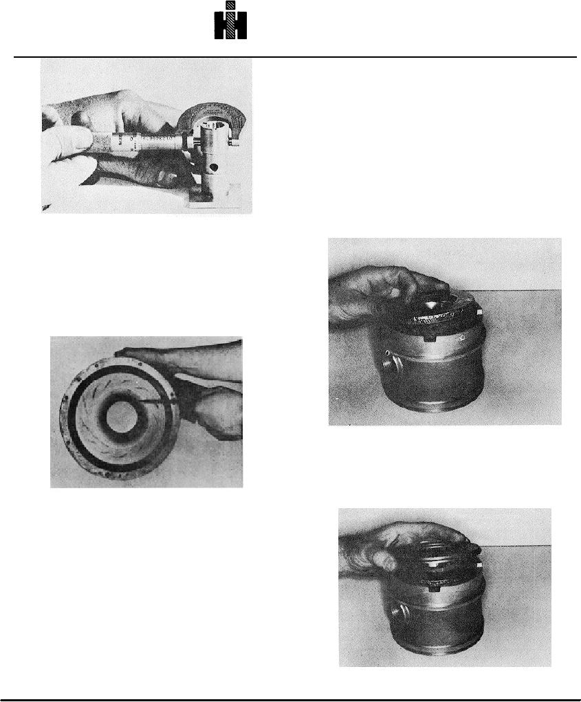
1. Use a piece of tubing or mandrel on shoulder of shaft
and check floating bearing end clearance on shaft. It
should be 0.005 to 0.009 inch [0.13 to 0.23 mm].
2. Position new metal covered insulation pad on turbine
end of bearing housing. Fig. 10-22.
Fig. 10-20, T-316. Measuring floating bearing O.D.
Collector Housing
Collector housing that is deeply scored from contact with
the compressor wheel, cannot be reused. Collector
housing contour is critical to proper turbocharger
performance. Fig.10-21.
Fig. 10-22, T-529. Installing insulation pad
3. Install heat shield on bearing housing. Fig. 10-23.
4. Position sealing rings In grooves on turbine end of
rotor shaft. Fig. 10-24.
Fig. 10-21, T-419 Inspecting compressor casing
If slight scratches or nicks are present, they may be
smoothed out with a very fine polishing cloth and the
collector housing may be reused. Discard If cracked or
distorted.
Miscellaneous
"V" clamps may be cleaned and reused unless they are
damaged.
Fig. 10-23, T-530. Installing heat shield
564