TRUCK SERVICE MANUAL
FUEL SYSTEM
11. Carefully move assembly and rotor support to a
press.
12. Lubricate rotor shaft O.D. with STP oil or equivalent,
position compressor wheel on shaft. Using a suitable
mandrel, place compressor wheel on shaft until wheel
seats against sleeve shoulder.
A press may be
necessary.
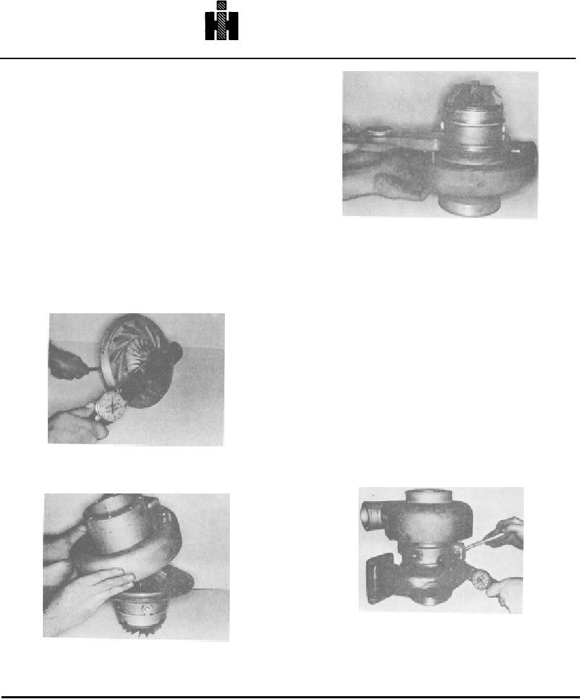
13. Install self-locking nut on rotor shaft. Place ST-1095
on torque wrench, hold nut with end wrench and turn
shaft with torque wrench to 20 to 24 ft-lb [27 to 33 Nm]
maximum torque. Fig. 10-33.
Caution: Over-torquing nut will deform shaft, distort
Fig. 10-35, T-543. Torquing oil seal/diffuser glate
thrust washer (if used) and cause oil leakage.
caoscrews incollector housing
14. Install collector housing on oil seal/diffuser plate and
bearing housing assembly, Fig. 10-34, align index marks,
15. Lubricate turbine casing bore with a heat-resistant
secure with lockwashers and capscrews. Tighten to 5 to
antiseize compound. Insert bearing housing and rotor
7ft-lb [7 to 10 Nm] torque. Fig. 10-35.
assembly in bore of turbine casing, aligning marks
scribed during disassembly until assembly seats on
shoulder.
16.
Position "V" bands around casings, centering
openings -of "V" bands over oil supply and drain ports,
secure with new bolts, flatwashers and self-locking nuts;
torque nuts to values listed in Specifications. Tap lightly
to seat "V" band while torquing nuts. Fig. 10-36. Check
clearance between turbine casing and V-band clamp.
There must be a minimum of 0.035 inch [0.89 mm].
Caution: Do not exceed recommended torque; this
causes clamp distortion and clamp loosening.
Clamp is not to be retorqued during operation.
17.
Check radial clearance at turbine end and
Fig. 10-33, T-437. Torquing self-locking nut on rotor
compressor end of turbocharger as follows:
shaft VT assembly
Fig. 10-36, T-421. Torquing "V" clamp bolts and nuts
Fig. 10-34, T-542. Installing oil seal/diffuser plate and
baring housing assembly in collector housing
567

