
TRUCK SERVICE MANUAL
FUEL SYSTEM
b. A flexible connection (hump hose or molded elbow)
should be provided between the turbocharger and
support point of the piping to prevent the compressor
casing from being rigidly retained.
c. No more than 5 ft. 9 inches [1.8 ml of unsupported air
intake tubing should be attached to the turbocharger.
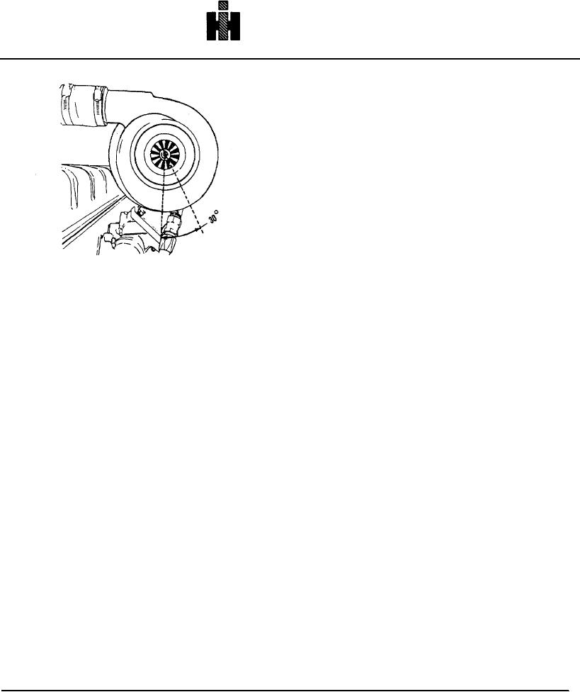
Fig. 10-40, T-333. Turbocharger mounting
7. Install hose connecting air outlet of turbocharger to
engine intake manifold connection.
8. Install air cleaner and exhaust piping.
9.
Check crankcase breather condition; excessive
crankcase pressure will cause turbocharger leakage.
Air And Exhaust Pipe Supports Both the air and
exhaust connections to a turbocharger require support
within a reasonable length to avoid excessive bending
moments on the turbocharger casing. They also require
a flexible joint between the turbocharger and the support
to compensate for movement, misalignment and thermal
expansion. The following are recommendations:
1. Exhaust Piping
a. The maximum bending moment of unsupported
piping at the outlet plane should not exceed 10 ft. lbs. [14
Nm .
b. A minimum of 12 inches [305 mm] of flexible
connection or two ball joints should be provided within
the first 4 ft. [1.2 m] of exhaust piping on turbocharged
engines to allow for thermal growth and to avoid
overstressing turbocharger components.
c. No more than 4 ft. [1.2 m] of unsupported exhaust
tubing or flexible connection should be attached to the
turbocharger.
2. Air Piping
a. The maximum bending moment of unsupported
piping at the compressor inlet plane should not exceed 5
ft. lbs. [7Nm].
569