TRUCK SERVICE MANUAL STEERING
Actuating Piston
SE-2394-4
Adapter (Fig. Ref. 4)
The actuating piston moves in the gear housing.
2. Place steering gear in a suitable overhaul stand.
There are two ports on the outside diameter of the valve
NOTE: When disassembling the gear, make
which direct the oil flow through the piston. The valve has
reference marks of your own so that the gear
about 1/32" linear motion within the piston, which permits
may be reassembled to the same adjustments.
the edges of the ports to seat against mating edges on
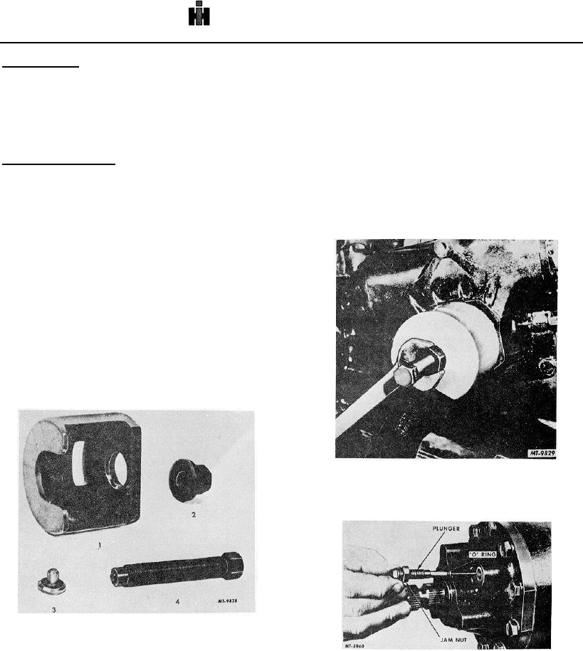
3. Using pitman arm puller SE-2394, Fig. 5, remove
the inside of the piston, directing the oil flow to either end
pitman arm from output shaft as follows: The
of the piston.
puller is applied to the arm as shown in Fig. 6.
Output Shaft and Pinion
With the puller screw contacting end of
One side of the piston assembly is equipped with
levershaft, turn hex flanged nut to remove pitman
teeth (rack) which are engaged with the pinion gear on
arm. Additional pulling effort can be obtained by
the output shaft. When the piston moves back and forth
turning both the flanged nut and forcing screw.
within the housing, the gear turns, providing the rotating
Where necessary install adapter at levershaft to
action of the pitman arm, which is connected to the
provide a seat for the forcing screw.
steering linkage.
Relief valve plungers (adjustable stops) are
provided at the bearing cap and cylinder head location
which automatically unload the hydraulic system when
the wheels are turned to either extreme direction. This
protects the mechanism from undue strain and damage
in that a clearance is provided at the wheel stops, Fig. 4.
DISASSEMBLY
1. To drain oil from the steering gear assembly,
disconnect the return hose from the pump and
turn the steering wheel completely to the right
and then to the left. This will remove most of the
oil from the housing.
Fig. 6
4. Loosen jam nut on the relief valve plunger and
remove the plungers from both ends of gear, Fig.
7.
Fig. 5 Pitman Arm Puller
Consists of:
SE-2394-1
Puller Body (Fig. Ref. 1)
SE-2394-2
Hex Flange Nut (Fig. Ref. 2)
Fig. 7
SE-2394-3
Forcing Screw (Fig. Ref. 3)
637

