TM 5-3805-254-20-1
ACCELERATOR CONTROL ROD - CONTINUED
ACTION
LOCATION
ITEM
REMARKS
ASSEMBLY
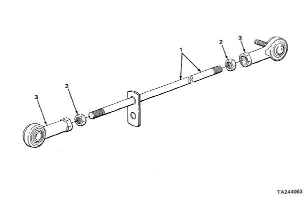
14. Accelerator control
Two locknuts (2)
Screw on until locknuts reach end of
rod (1)
threads.
15.
Ball joint
a.
Screw on until accelerator control rod is
assemblies (3)
same length, measured before disas-
sembly (step 6).
Ball joint assemblies must be threaded
evenly on accelerator control rod.
b.
Position ball joints as shown.
16.
Two locknuts (2)
a.
Turn until locknuts touch ball joints.
b.
Hand tighten to keep ball joint assem-
blies from moving.
INSTALLATION
17. Lever assembly (4)
Accelerator control
Put in.
rod (1)
2-554