
TM 5-3805-264-13&P
0005
DUMPING LOAD - Continued
b.
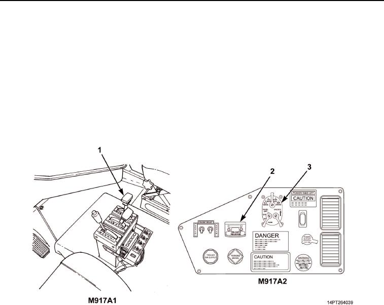
Return hydraulic control lever (Figure 4, Item 1) to N (Neutral) position.
4.
After Dumping
CAUTION
Always disengage PTO when hydraulic power is no longer needed. Failure to comply
may result in damage to equipment.
a.
Disengage PTO (TM 9-2320-363-10 or TM 9-2320-302-10).
b.
Turn off main light switch (Figure 4, Item 3).
c.
Slide tailgate release control valve lever (Figure 4, Item 2) right to LOCK position.
Figure 4. Hydraulic Control Lever and Dashboard Controls and Indicators.
03/15/2011Rel(1.10)root(opusualwp)wpno(O1000226413)