
TM 5-3805-264-13&P
0017
Table 1. Operator Preventive Maintenance Checks and Services (PMCS) - Continued.
ITEM TO BE
EQUIPMENT
ITEM
CHECKED OR
NOT READY/
NO.
INTERVAL
SERVICED
PROCEDURE
AVAILABLE IF:
WARNING
13
After
Hydraulic
Reservoir
To prevent burns, use caution when
removing fill cap of hydraulic reservoir when
hydraulic fluid is hot. Avoid contact with hot
hydraulic oil. Use extreme care when
draining hydraulic oil. Failure to comply may
result in personnel injury or death.
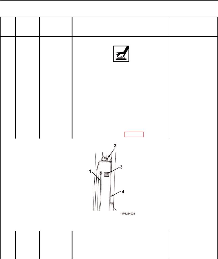
1. With engine off and dump body lowered, check sight
tube (Figure 8, Item 1) to determine level of hydraulic
oil in reservoir (Figure 8, Item 4). Level should be even
with FULL mark on oil level decal (Figure 8, Item 3). If
level is low, remove fill cap (Figure 8, Item 2). Remove
any debris from strainer with a clean rag. Add oil
through fill cap opening until level is even with FULL
mark on decal. Install fill cap (WP 0073).
Figure 8. Hydraulic Reservoir.
2. Run engine at idle speed and engage PTO
(TM 9-2320-363-10 or TM 9- 2320-302-10). Check
filter service indicator gauge (Figure 9, Item 1). If
gauge needle is in RED zone, hydraulic oil filter
element needs replacing. Notify your supervisor.
03/15/2011Rel(1.10)root(pmcswp)wpno(I1000226413)