
TM 5-3805-264-13&P
0024
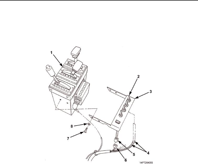
INSTALLATION
1.
Connect four wiring harness leads (Figure 3, Item 4) to toggle switches (Figure 3, Item 2).
2.
Connect wiring harness connector (Figure 3, Item 6) to indicator light connector (Figure 3, Item 5).
3.
Install MCS control unit (Figure 3, Item 3) on shift tower (Figure 3, Item 1) with four washers
(Figure 3, Item 8) and screws (Figure 3, Item 7).
Figure 3. MCS Control Unit Installation.
END OF TASK
FOLLOW-ON MAINTENANCE
1.
Connect batteries (TM 9-2320-363-20-1, TM 9-2320-363-20-2).
2.
Turn master battery switch ON (TM 9-2320-302-10).
END OF TASK
END OF WORK PACKAGE
03/15/2011Rel(1.10)root(maintwp)wpno(M1000826413)