
TM 5-3805-264-13&P
FIELD MAINTENANCE
MATERIAL CONTROL SYSTEM (MCS) SWITCH REPLACEMENT
INITIAL SETUP:
Tools and Special Tools
Equipment Condition (cont.)
General Mechanic's Tool Kit
Air system drained (TM 9-2320-302-10)
(WP 0113, Table 1, Item 12)
Master battery switch OFF (TM 9-2320-302-10)
Materials/Parts
Marker Tags (WP 0112, Table 1, Item 36)
References
Equipment Condition
Batteries disconnected (TM 9-2320-363-20-1,
TM 9-2320-363-20-2)
REMOVAL
1.
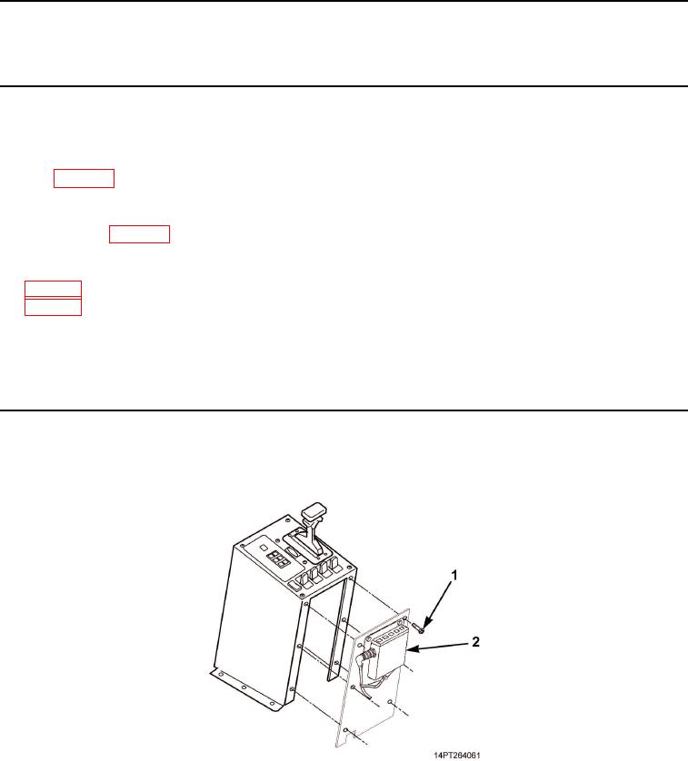
Remove six screws (Figure 1, Item 1) and rear panel (Figure 1, Item 2).
Figure 1. MCS Rear Panel Removal.
03/15/2011Rel(1.10)root(maintwp)wpno(M1000926413)