
TM 5-3805-264-13&P
0030
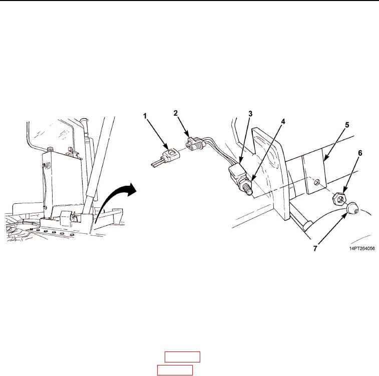
INSTALLATION
1.
Install jamnut (Figure 2, Item 4) on transport lock switch (Figure 2, Item 3) in same position as noted during
removal.
2.
Position transport lock switch (Figure 2, Item 3) through hole in chassis mount (Figure 2, Item 5) and install
nut (Figure 2, Item 6) and button (Figure 2, Item 7).
3.
Connect transport lock switch connector (Figure 2, Item 2) to wiring harness connector (Figure 2, Item 1).
4.
Install new tiedown straps, as required.
Figure 2. Transport Lock Switch Installation.
END OF TASK
FOLLOW-ON MAINTENANCE
1.
Connect batteries (TM 9-2320-363-20-1, TM 9-2320-363-20-2).
2.
Turn master battery switch ON (TM 9-2320-302-10).
3.
Remove body props and lower dump body (WP 0005).
4.
Check operation of transport lock switch (WP 0005).
END OF TASK
END OF WORK PACKAGE
03/15/2011Rel(1.10)root(maintwp)wpno(M1000526413)