
TM 5-3805-264-13&P
0031
INSTALLATION
1.
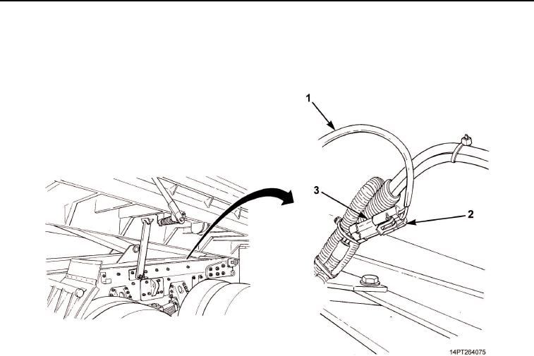
Position wiring harness (Figure 3, Item 1) between points of connection.
2.
Connect wiring harness connector (Figure 3, Item 2) to chassis wiring harness connector (Figure 3, Item 3).
Figure 3. Beacon Warning Light Wiring Harness Installation.
3.
Route wiring harness (Figure 4, Item 3) along inner surface of passenger's side dump body frame rail
(Figure 4, Item 8) and through grommet (Figure 4, Item 7) at front of passenger's side dump body
(Figure 4, Item 9).
4.
Route wiring harness (Figure 4, Item 3) up dump body (Figure 4, Item 9) and cab shield (Figure 4, Item 2)
Secure with clamps (Figure 4, Item 5) and nuts (Figure 4, Item 4) on welded studs (Figure 4, Item 6).
5.
Secure wiring harness (Figure 4, Item 3) along inner surface of passenger's side dump body frame rail
(Figure 4, Item 8) with clamps (Figure 4, Item 5) and nuts (Figure 4, Item 4) on welded studs
(Figure 4, Item 6).
6.
Install wiring harness (Figure 4, Item 3) through cab shield grommet (Figure 4, Item 1).
7.
Install new tiedown straps.
03/15/2011Rel(1.10)root(maintwp)wpno(M1001226413)