
TM 5-3805-264-13&P
0045
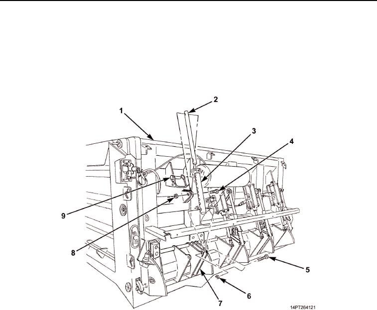
REMOVAL
1.
Remove locking pin (Figure 1, Item 9) from adjustment tube (Figure 1, Item 3).
2.
Remove locknut (Figure 1, Item 6), screw (Figure 1, Item 5), and adjustment tube (Figure 1, Item 3) from
MCS gate (Figure 1, Item 7). Discard locknut.
3.
Remove locknut (Figure 1, Item 8), screw (Figure 1, Item 4), and upper tube (Figure 1, Item 2) from MCS
tailgate (Figure 1, Item 1). Discard locknut.
Figure 1. Adjustment Tube Removal.
END OF TASK
INSTALLATION
1.
Install upper tube (Figure 2, Item 2) on MCS tailgate (Figure 2, Item 1) with screw (Figure 2, Item 4) and
new locknut (Figure 2, Item 8).
2.
Position adjustment tube (Figure 2, Item 3) over upper tube (Figure 2, Item 2). Install adjustment tube on
MCS gate (Figure 2, Item 7) with screw (Figure 2, Item 5) and new locknut (Figure 2, Item 6).
CAUTION
Outer passenger's and outer driver's side adjustment tube locking pins must be installed
with pin heads to outside. If incorrectly installed, ends of pins will protrude and become
bent. Failure to comply may result in damage to equipment.
3.
Install locking pin (Figure 2, Item 9) on adjustment tube (Figure 2, Item 3).
03/15/2011Rel(1.10)root(maintwp)wpno(M1002626413)