
TM 5-3805-264-13&P
0050
ASSEMBLY
WARNING
Eye protection and gloves must be worn when using grease or sealing compound. Failure
to comply may result in personnel injury.
1.
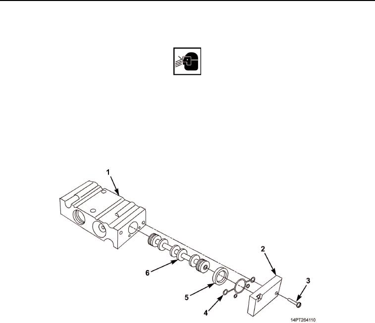
Apply a light coat of grease to valve (Figure 6, Item 6).
2.
Install valve (Figure 6, Item 6) in valve body (Figure 6, Item 1).
3.
Install gasket (Figure 6, Item 4) and plastic insert (Figure 6, Item 5) on end cap (Figure 6, Item 2).
4.
Position end cap (Figure 6, Item 2) on valve body (Figure 6, Item 1) and install two screws
(Figure 6, Item 3).
Figure 6. Valve Body End Cap and Valve Assembly.
03/15/2011Rel(1.10)root(maintwp)wpno(M1002326413)