
TM 5-3805-264-13&P
0050
ASSEMBLY - Continued
8.
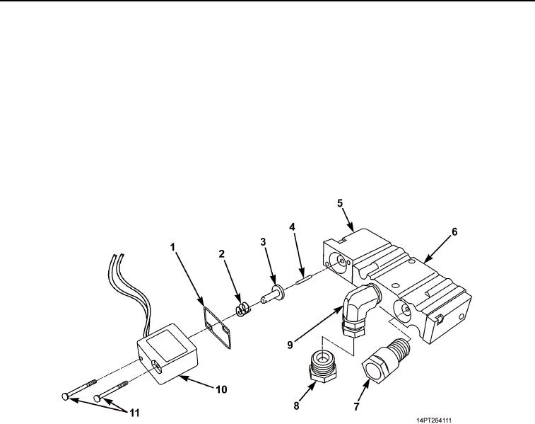
Apply pipe sealing compound to elbow (Figure 8, Item 9) and install elbow on valve body (Figure 8, Item 6).
9.
Install gasket (Figure 8, Item 1) on filter housing (Figure 8, Item 5).
10.
Install pin (Figure 8, Item 4) in plunger (Figure 8, Item 3).
11.
Position plunger (Figure 8, Item 3) and spring (Figure 8, Item 2) on solenoid (Figure 8, Item 10).
12.
Position solenoid (Figure 8, Item 10) on filter housing (Figure 8, Item 5) and install two screws
(Figure 8, Item 11).
13.
Apply pipe sealing compound to fitting (Figure 8, Item 8) and install fitting on elbow (Figure 8, Item 9).
14.
Apply pipe sealing compound to fitting (Figure 8, Item 7) and install fitting on valve body (Figure 8, Item 6).
Figure 8. Valve Body Fittings and Solenoid Assembly.
03/15/2011Rel(1.10)root(maintwp)wpno(M1002326413)